

U2105 on 2008-2014 Cadillac CTS: Causes and Fixes for Lost Communication
Code U2105 on a 2008-2014 Cadillac CTS most often indicates a poor connection at the main transmission harness connector (X1), located on the driver's side of the transmission. Inspecting, cleaning, and securing the pins in this connector is the most common fix, as documented in GM TSB PIC4740F, and often resolves the issue without replacing any parts.
- U2105 on a 2008-2014 CTS is a network communication code, not a specific mechanical failure.
- Before considering expensive module replacements, always perform the checks outlined in TSB PIC4740E, focusing on the main transmission connector.
- Symptoms are often severe, including harsh shifting and a no-start condition, but the fix can be as simple as reseating a connector pin.
- This code is frequently accompanied by a long list of other communication codes (U-codes), which all point back to the same root network issue.
What's Unique About the 2008-2014 Cadillac CTS

The second-generation Cadillac CTS (2008-2014) is specifically known for electrical issues related to the main transmission harness connector (X1). A widely circulated General Motors Technical Service Bulletin (TSB), most recently PIC4740F, directly addresses that unseated pins, corrosion, or a poor fit at this connector can cause a loss of communication. This triggers code U2105 and a host of other related network codes, often resulting in harsh shifting and a "Service Stabilitrak" message. This makes a physical wiring inspection at the transmission connector much more critical on this platform compared to others where the code might immediately suggest module failure.
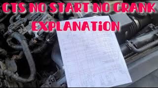
🎬 See this explanation of no-start issues caused by a bad ECM.Diagnostic Flowchart
Tap your situation to follow the diagnostic path that matches what you're seeing on this vehicle.
Symptoms You May Notice
- Check Engine Light (SES light) is on.
- Transmission warning light on
- "Service Stabilitrak" or "Traction Control Off" message on the Driver Information Center (DIC).
- "Reduced Engine Power" message displayed.
- Transmission shifts harshly or is stuck in one gear (limp mode).
- Vehicle may not crank or start.
- Inability to communicate with the TCM or ECM with a scan tool.
- Multiple other warning lights may illuminate on the dash.
- Door locks may cycle while driving.
- Replacing the Transmission Control Module (TCM) without first thoroughly inspecting the X1 connector and wiring harness. The TSB clearly indicates the wiring is a more frequent point of failure.
- Replacing the ECM based on the generic definition of U2105 ('Lost Communication With ECM') without considering the full context of other stored codes (like U0101/U2106) that point toward the transmission.
Most Likely Causes

- Poor Connection at Transmission Harness Connector (X1) 🔴 High Probability A known issue documented in GM TSB PIC4740E and its successor, PIC4740F. The connector pins can become unseated, corroded, or have a poor fit, causing intermittent communication loss. The connector is exposed to the elements on the driver's side of the transmission.
How to confirm: Disconnect the X1 connector at the transmission. Visually inspect the male and female terminals for corrosion, moisture, or damage. Gently tug on each individual wire going into the connector to ensure the pins are fully seated and locked in place. A loose pin is a very common cause.
Typical fix: Reseat the connector and any loose pins. Clean any corrosion with electrical contact cleaner. If the connector or terminals are damaged, they will need to be repaired or replaced. A zip tie is often used by owners and shops to apply pressure and ensure the connector remains fully seated.
Est. part cost: $0-$50 - Chafed or Damaged Wiring Harness 🟡 Medium Probability TSB PIC4740F specifically calls out an inspection of the harness securing bracket on the passenger side of the transmission bell housing, where the harness can rub through and short circuit.
How to confirm: Visually inspect the entire wiring harness leading to the transmission for any signs of rubbing, melting, or physical damage, paying close attention to the bracket area mentioned in the TSB.
Typical fix: Repair the damaged section of wire using solder and heat shrink. Protect the repaired area from future damage using a protective loom or by rerouting it away from the chafe point.
Est. part cost: $5-$100 - Failed Transmission Control Module (TCM) ⚪ Low Probability While less common than wiring issues, the internal-to-the-transmission TCM can fail, causing a total loss of communication. This is a last resort after all wiring has been confirmed good.
How to confirm: After confirming all wiring, power, and grounds to the TCM are good (continuity and voltage checks), the module itself becomes the primary suspect. This diagnosis requires a professional with advanced tools to rule out network issues.
Typical fix: Replace the Transmission Control Module. This is a complex job as the TCM is located inside the transmission oil pan. The replacement module must be programmed to the vehicle's VIN.
Est. part cost: $200-$700
Rare But Worth Checking
- Failed Engine Control Module (ECM) or Body Control Module (BCM): Since the CAN bus is a network, a failure in another primary module like the ECM or BCM can sometimes disrupt communication and trigger codes in other modules. The BCM in particular acts as a gateway module for communication buses. This is rare and should only be considered after all transmission-related wiring and the TCM itself have been ruled out.
- Poor Grounds: A bad ground connection for the ECM or TCM can cause a host of communication issues. Check the main ground points on the engine block and chassis for corrosion and tightness. On CTS-V models, ground G110 has been known to cause issues if disturbed by aftermarket cold air intake installations.
- Low Battery Voltage: A weak or failing battery can cause numerous, seemingly unrelated electronic issues and communication codes on modern vehicles. If the battery is old or has been recently drained, it should be tested and replaced if necessary before proceeding with more complex diagnostics.
Diagnosis Steps
- Scan the vehicle for all stored Diagnostic Trouble Codes (DTCs). Note all communication (U-codes) and transmission (P-codes) present. Pay close attention to codes U0101 and U2106 appearing with U2105.
- Disconnect the negative battery terminal for safety.
- Follow the instructions in TSB PIC4740F: Locate the main transmission harness connector (X1) on the driver's side of the transmission case.
- Disconnect the X1 connector. Inspect the terminals on both the harness side and the transmission side for any signs of corrosion, moisture, bent pins, or damage. Clean with electrical contact cleaner if necessary.
- Carefully and gently tug on each individual wire going into the connector to ensure the pins are fully seated and locked. A loose pin is a very common cause.
- Inspect the wiring harness near the transmission bell housing (passenger side) for any signs of chafing or damage, particularly around securing brackets as noted in the TSB.
- If no physical wiring issues are found, reconnect the battery and connector. With the key on, check for battery voltage and good ground connections at the appropriate TCM connector pins using a multimeter and wiring diagram.
- If power and grounds are good, the issue may be with the CAN bus wiring itself (check for 60 ohms of resistance across CAN High and CAN Low with the battery disconnected) or an internal failure of the TCM.
- After any repairs, clear all DTCs and perform a test drive to ensure the problem is resolved.
Parts You'll Likely Need

- Transmission Harness Connector Repair Kit (Pigtail)
(OEM #ACDelco PT2389 (GM 13580119) - Varies by specific application, verify before purchase.)— If the connector housing or terminals are corroded or damaged beyond cleaning, a new pigtail is needed to be spliced into the harness. Often, no parts are needed and simply securing the existing connector fixes the issue.
Trusted brands: ACDelco, Dorman
OEM price range: $40-$100
Aftermarket price range: $20-$60 - Transmission Control Module (TCM)
(OEM #e.g., 24256960 (Varies significantly by year and transmission type, VIN match is critical))— This is the part to replace if all wiring and connections have been confirmed to be in good condition, but communication with the module cannot be established. It is located inside the transmission.
Trusted brands: ACDelco (GM Genuine)
OEM price range: $400-$700
Aftermarket price range: $200-$500
Related Codes That Often Appear With This One
- U0101 — This is the standard SAE code for 'Lost Communication with TCM'. U2105 and U2106 are manufacturer-specific variations often seen with it.
- P0700 — This code means the TCM has requested the check engine light to be turned on. It's a general code indicating a fault is stored within the TCM.
- U0073 — This is a general 'Controller Area Network (CAN) Bus Communication' error, indicating a problem on the vehicle's primary communication network.
- U2100 — Another general CAN Bus Communication code, often stored alongside more specific communication loss codes.
- U2106 — This code specifically means 'Lost Communication With Transmission Control Module (TCM)' and is often seen with U2105.
- U0121 — Lost Communication With Anti-Lock Brake System (ABS) Control Module. This often appears because the Stabilitrak system relies on both the TCM and ABS modules to function.
Technical Service Bulletins (TSBs) & Recalls
- PIC4740E: Addresses multiple communication DTCs, including U2105, and directs technicians to inspect the transmission X1 connector terminals for a loose or poor fit.
- PIC4740F: Supersedes PIC4740E, updating the model years and adding a specific check for a chafed harness at a bracket near the bell housing for Cadillac CTS and ATS models.
Platform-Specific Known Issues
- A Technical Service Bulletin (PIC4740F, superseding PIC4740E) was issued by GM for a wide range of vehicles, including the 2008-2015 CTS, for symptoms including no-start, hard shifting, and multiple warning lights caused by unseated pins in the transmission X1 connector.
Mechanic-Grade Diagnostic Values
- High-Speed GMLAN Bus Resistance — expected: 60 Ohms (+/- 5 Ohms). Failure: A reading of 120 Ohms indicates an open in the bus or a missing termination resistor. A reading significantly less than 60 Ohms indicates the CAN High and Low wires are shorted together.
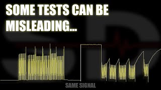
- High-Speed GMLAN Bus Voltage (Key On, Engine Off) — expected: Both CAN High (Pin 6 at DLC) and CAN Low (Pin 14 at DLC) should be at approximately 2.5V when the bus is at rest (inactive).. Failure: When communicating, CAN High should toggle to ~3.5V and CAN Low should toggle to ~1.5V. A short to ground will show 0V on the affected line, while a short to power will show battery voltage. These fluctuating voltages are best viewed with an oscilloscope.
Scan Tool Commands That Help
- GDS2 (Global Diagnostic System 2): Data Bus Diagnostic Tool — This tool, which integrates with GDS2, can actively poll the CAN bus and report which modules are communicating and which are not. This helps create a starting point for diagnosis by identifying the exact module that is offline.
- GDS2 (Global Diagnostic System 2): Clear All DTCs / Clear Secured High Voltage DTCs — After a repair, some communication codes, especially on related platforms, may be 'secured' and require a specific routine in the dealer tool to fully clear them and restore normal operation. While more common for hybrid systems, it's a function to be aware of for stubborn communication faults.
Wiring & Ground Locations

- X1 Connector — The main 16-pin electrical connector on the driver's side of the transmission case.. This is the primary point of failure documented in TSB PIC4740E/F. Poorly seated pins, corrosion, or damage here directly interrupts communication between the TCM and the rest of the vehicle.
- Harness Securing Bracket — On the passenger side of the vehicle, where the transmission bell housing attaches to the engine block.. The TSB specifically calls out this location as a potential chafe point where the wiring harness can rub through and short circuit, causing communication loss.
- G110 — Engine ground point, often used as a mounting point for aftermarket Cold Air Intake brackets.. On CTS-V models, using this ground for aftermarket accessories can create a poor ground connection, leading to various electrical issues including Service Power Steering messages and communication DTCs like U0121. While not directly U2105, it demonstrates the sensitivity of the vehicle's ground network.
- DLC (Data Link Connector) — Under the driver's side dashboard.. Pins 6 (CAN High) and 14 (CAN Low) are used for high-speed network diagnostics. Technicians test resistance and voltage here to assess the health of the entire GMLAN bus.
Real Owner Repair Stories
- ScannerDanner Forum (2009 Cadillac CTS) — No communication with scanner on high-speed CAN bus. Multiple warning lights.
❌ Tried (didn't work) Initial resistance checks of the CAN bus did not reveal a clear short or open circuit.
✅ What actually fixed it The ABS module connector had lint jammed in it. The debris was not enough to significantly alter resistance readings but was sufficient to disrupt high-speed data communication. Cleaning the connector restored normal operation.
Model Year Variations Within This Range
- 2012-2014: In 2012, the base 3.6L V6 engine was updated from the LLT to the LFX. While the transmission and general architecture remained the same, there can be minor differences in engine-side wiring and component locations. The core issue with the transmission X1 connector and harness chafing remains common to both engine types within this generation.
Helpful Videos
Used OEM Parts in Stock


New Aftermarket Parts Available

The information in this article is provided for general reference and educational purposes only. Vehicle specifications, procedures, and part compatibility can vary by production date, trim level, and region. Always consult your vehicle's factory service manual and verify part numbers before purchasing or performing repairs. Safety-critical components such as airbags, seat belts, and braking systems should be installed by a qualified professional.
- Cadillac CTS:
- 🎬 Helpful Videos
- 🛍️ Shop This Part
- What's Unique About the 2008-2014 Cadillac CTS
- Diagnostic Flowchart
- Symptoms You May Notice
- Most Likely Causes
- Rare But Worth Checking
- Diagnosis Steps
- Parts You'll Likely Need
- Related Codes That Often Appear With This One
- Technical Service Bulletins (TSBs) & Recalls
- Platform-Specific Known Issues
- Mechanic-Grade Diagnostic Values
- Scan Tool Commands That Help
- Wiring & Ground Locations
- Real Owner Repair Stories
- Model Year Variations Within This Range
- 🎟️ Get 5% Off