

U0073 on 2008-2014 Cadillac CTS: Control Module Communication Failure Causes and Fixes
On a 2008-2014 Cadillac CTS, code U0073 is most often caused by loose or corroded terminals in the transmission's main electrical connector (X1), located on the driver's side of the transmission. Inspecting, cleaning, and tightening these terminals is the most likely fix and can often be done for a very low cost, as documented in GM TSB #PIC4740E.
- U0073 on a 2008-2014 CTS is a serious network communication code.
- The most likely cause is a poor connection at the main transmission wiring harness connector (X1), as per a GM TSB.
- Always inspect wiring and connectors thoroughly before considering replacing expensive control modules.
- Due to the risk of stalling or safety system failure, the vehicle should be repaired promptly.
- Diagnosis can be complex and may require professional-level tools if the initial visual inspection doesn't reveal the problem.
What's Unique About the 2008-2014 Cadillac CTS

For the second-generation Cadillac CTS, this code is specifically called out in a GM 🎬 Watch: What code U0073 really means for your electrical system Technical Service Bulletin (TSB #PIC4740E) related to a vulnerable connector. The TSB identifies the transmission's main X1 electrical connector as a common failure point where terminals can become loose or corroded, disrupting the entire communication network. This makes a wiring or connector issue a much higher probability on this platform compared to a random module failure. The bulletin applies to a wide range of GM vehicles but is a well-documented problem on the CTS.
Diagnostic Flowchart
Tap your situation to follow the diagnostic path that matches what you're seeing on this vehicle.
Symptoms You May Notice
- Check Engine Light is on
- "Service Stabilitrak" message on the dash
- ABS and Traction Control warning lights are on
- Harsh or erratic transmission shifting
- Loss of power or engine hesitation, vehicle enters 'limp mode'
- Instrument cluster gauges may drop to zero or show dashes
- No-start or no-crank condition
- Intermittent failure of electrical accessories
- Door locks cycling while driving
- Radio display may go blank or reset
- Replacing the Engine Control Module (ECM) or Transmission Control Module (TCM) without first thoroughly inspecting all related wiring and connectors. The problem is far more likely to be in the harness or the X1 connector than the module itself.
Most Likely Causes

- Loose or Corroded Terminals in Transmission Connector (X1) 🔴 High Probability This is a known issue documented by GM in Technical Service Bulletin #PIC4740E. The connector's location on the driver's side of the transmission exposes it to vibration, heat, and moisture, leading to poor connections over time. The female terminals can spread, losing tension on the male pins.
How to confirm: Visually inspect the pins and terminals inside the large X1 connector on the transmission. Look for any signs of green or white corrosion, moisture, or pins that appear spread apart or pushed back into the connector. A key test is to gently tug on each wire to ensure the terminals are fully seated. The CAN bus wires are typically a twisted pair, often Tan and Tan/Black or Green and Green/White.
Typical fix: Disconnect the battery. Unplug the connector, clean the terminals with an electrical contact cleaner, and use a special terminal pick tool to gently tighten (re-tension) any loose female terminals. Re-seat the connector firmly and add dielectric grease to the seal to prevent future moisture intrusion. If terminals are badly corroded, they may need to be replaced.
Est. part cost: $5-$20 - Damaged CAN Bus Wiring Harness 🟡 Medium Probability Wiring harnesses can rub against engine or chassis components, causing wires to chafe and short out. TSB #PIC4740E specifically calls out inspecting the harness securing bracket on the passenger side where the transmission bell housing attaches to the engine block for potential chafing on CTS models.
How to confirm: Perform a detailed visual inspection of the wiring harness, particularly around the engine, transmission, and the specific areas mentioned in the TSB. Look for any areas where the protective loom is worn through or wires are exposed.
Typical fix: Repair the damaged section of wire. This involves cutting out the bad section, soldering in a new piece of wire of the same gauge, and protecting the repair with heat-shrink tubing.
Est. part cost: $10-$30 - Failed Control Module ⚪ Low Probability While less common, any module on the network (ECM, TCM, BCM, ABS) can fail internally and disrupt communication for all other modules. Water intrusion from clogged sunroof drains is a known issue that can damage modules located in the cabin.
How to confirm: This requires an advanced scan tool to see which modules are not communicating. A technician may disconnect modules one by one to see if communication is restored to the rest of the network.
Typical fix: Replace the faulty module. This often requires programming the new module to the vehicle with specialized equipment.
Est. part cost: $300-$1500 - Poor Battery Voltage or Ground Connection ⚪ Low Probability Control modules require a stable voltage to operate. A weak battery, failing alternator, or corroded main ground can cause unpredictable electronic issues, including network communication faults.
How to confirm: Test the battery voltage with the engine off (should be >12.4V) and with the engine running (should be 13.7V-14.7V). Inspect the main battery cables and chassis ground points for corrosion or looseness.
Typical fix: Charge or replace the battery, replace the alternator, or clean/tighten the ground connections.
Est. part cost: $0-$400
Rare But Worth Checking
- Failed CAN Bus Termination Resistor: The CAN bus has a 120-ohm resistor at each end (typically in the ECM and another module like the BCM or instrument cluster). If one fails, the network's total resistance will be incorrect (reading 120 ohms instead of the correct ~60 ohms when measured at the OBD-II port), causing communication to fail. This is rare but a key check in advanced diagnostics.
- Interference from Aftermarket Electronics: Improperly installed aftermarket alarms, remote starters, or audio equipment can interfere with the CAN bus wiring and cause communication errors. This is especially true if they are tapped into the CAN wiring instead of using proper integration harnesses.
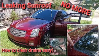
- Water Intrusion from Clogged Sunroof Drains: A known issue on the CTS platform is clogged sunroof drains, which can cause water to leak inside the cabin and onto critical electronic components, including the Body Control Module (BCM) or fuse boxes, leading to widespread communication failures.
Diagnosis Steps

- Scan all vehicle modules for stored trouble codes. Note which modules are not responding, which often includes the ECM and TCM.
- Check the battery and charging system to ensure proper voltage (>12.4V off, 13.7-14.7V running).
- Following TSB #PIC4740E, locate and disconnect the transmission X1 connector on the driver's side of the transmission. Thoroughly inspect the male and female terminals for corrosion, damage, pushed-out pins, or spread female terminals.
- Gently tug on each wire going into the back of the X1 connector to ensure they are fully seated and locked.
- If the connector looks good, inspect the main wiring harness for any signs of physical damage, chafing, or rubbing, paying close attention to the area near the bell housing bracket on the passenger side.
- If no visible issues are found, use a multimeter to check for 60 ohms of resistance across pins 6 (CAN High) and 14 (CAN Low) at the OBD-II port with the battery disconnected. A reading of 120 ohms suggests a break in the circuit or a failed termination resistor, while a reading near 0 ohms indicates a short between the two lines.
- If wiring and resistance are correct, a more advanced tool like an oscilloscope may be needed to check the data signal on the CAN lines for noise or a short.
- As a final step, a technician may disconnect modules one by one to isolate a faulty module that might be bringing down the network.
Parts You'll Likely Need
- Transmission Wiring Harness Connector Terminals
(OEM #Varies by pin location, consult dealer. A full connector pigtail like ACDelco PT1626 may be an option if the housing is damaged.)— The female terminals inside the connector can spread open, causing a poor connection. They may need to be replaced if they cannot be retensioned.
Trusted brands: ACDelco, GM Genuine Parts
OEM price range: $5-$15 per terminal
Aftermarket price range: $2-$10 per terminal - Electrical Contact Cleaner — Essential for safely cleaning corrosion from connectors and terminals without leaving a residue.
Trusted brands: CRC, WD-40 Specialist
OEM price range: $10-$20
Aftermarket price range: $8-$15 - Transmission Control Module (TCM)
(OEM #e.g., GM Part #88988938 (example, verify by VIN))— If diagnostics confirm the TCM has failed internally
Trusted brands: ACDelco, GM Genuine Parts
OEM price range: $400-$800
Aftermarket price range: $250-$600
Related Codes That Often Appear With This One
- U0100 — Lost Communication With ECM/PCM
- U0101 — Lost Communication with TCM
- U0121 — Lost Communication With Anti-Lock Brake System (ABS) Control Module
- U0140 — Lost Communication With Body Control Module
- C0561 — System Disabled Information Stored (related to Stabilitrak)
- P0700 — Transmission Control System (MIL Request)
Technical Service Bulletins (TSBs) & Recalls
- PIC4740E: Addresses a wide range of communication DTCs, including U0073, and points directly to inspecting the transmission X1 connector terminals for being unseated or loose. It also advises checking for harness chafing near the bell housing on the CTS.
Platform-Specific Known Issues
- Owner Experience with Sunroof Leak: A 2008 CTS owner on Reddit reported a cascade of communication codes (U0073 included) and limp mode behavior after their sunroof drains clogged and water drenched the interior. This demonstrates that while the X1 connector is a primary suspect for U0073, water intrusion damaging other modules is a real-world cause on this platform.
- TSB PIC4740E Focus: The existence of a specific TSB that lists U0073 and directly points to the transmission connector and harness chafing spots is the single most important vehicle-specific issue. It elevates a common wiring check to the primary diagnostic step for any technician or owner seeing this code on a 2008-2014 CTS.
Mechanic-Grade Diagnostic Values
- CAN Bus Resistance (Battery Disconnected) — expected: ~60 Ω. Failure: A reading of ~120 Ω indicates an open circuit or missing terminator. A reading near 0 Ω indicates a short between the CAN high and low lines.
- CAN Bus Voltage (Key On, Engine Off) — expected: CAN High (Pin 6 to Ground): ~2.5-3.5V; CAN Low (Pin 14 to Ground): ~1.5-2.5V. Both should average near 2.5V.. Failure: Voltages stuck high, low, or at 0V indicate a short to power or ground, or a faulty transceiver. An oscilloscope is required for a definitive analysis of the waveform.
Scan Tool Commands That Help
- GDS2 / Tech2: Module Status / Device List / Class 2 Message Monitor — This is a primary diagnostic step. After connecting the scan tool, this function polls all expected control modules on the network. The resulting list will show which modules are communicating and, more importantly, which ones are not responding. This helps to isolate the location of the fault (e.g., if the TCM is not responding, the fault is likely in the wiring to the TCM or the TCM itself).
Wiring & Ground Locations

- X1 Connector — The main 16-pin electrical connector on the driver's side of the transmission housing.. This is the specific connector identified in GM TSB #PIC4740E as a primary failure point for loose or corroded terminals that cause code U0073 and numerous other communication codes.
- G103 — Typically located at the left rear of the engine compartment, on the cowl, above the brake booster.. This ground point serves the Body Control Module (BCM), Instrument Panel Cluster (IPC), and the Data Link Connector (DLC) itself. A poor connection here can disrupt communication across multiple systems.
- G101 — Typically located on the lower front of the engine block.. This is a primary ground for the Engine Control Module (ECM) and Transmission Control Module (TCM). A loose or corroded G101 can cause intermittent power loss to these critical modules, triggering communication faults.
- OBD-II DLC Pins 6 & 14 — Under the driver's side dashboard. Pin 6 is CAN High, and Pin 14 is CAN Low.. These are the primary test points for measuring the overall health of the high-speed CAN bus with a multimeter or oscilloscope without having to access individual modules.
"I Checked Everything" — The Actual Cause
- The '60 Ohm Trap': A common diagnostic mistake is to measure 60 ohms across the CAN bus (at the OBD-II port with the battery disconnected), see the correct value, and assume the wiring is good. However, this static test does not reveal intermittent issues that occur with heat or vibration, nor does it detect a faulty module transceiver that only fails when powered on. A 'good' 60-ohm reading only confirms the two terminating resistors are present and the bus isn't completely shorted or open at that moment. The fault can still be present, requiring dynamic testing with an oscilloscope or isolating modules one-by-one.
OEM Part Supersession History
Varies→ACDelco PT1366 (GM 15306311)— Repair part
Heads up: This is a generic multi-purpose 2-wire pigtail connector. While not a direct replacement for the entire X1 transmission connector, it may be used by technicians to replace individual damaged connector terminals/wires within a harness, such as for the CAN bus lines, if the original connector housing is intact.
Model Year Variations Within This Range
- 2008-2011 vs 2012-2014: The 3.6L V6 engine was updated in 2012 from the LLT to the LFX. This change included a switch from a Bosch ECM (on the LLT) to a Delphi ECM (on the LFX). While the U0073 code's primary cause related to the transmission connector remains consistent, any diagnostics involving the ECM, its specific wiring, or its software are different between these two groups of model years.
Helpful Videos

Used OEM Parts in Stock


New Aftermarket Parts Available

The information in this article is provided for general reference and educational purposes only. Vehicle specifications, procedures, and part compatibility can vary by production date, trim level, and region. Always consult your vehicle's factory service manual and verify part numbers before purchasing or performing repairs. Safety-critical components such as airbags, seat belts, and braking systems should be installed by a qualified professional.
- Cadillac CTS:
- 🎬 Helpful Videos
- 🛍️ Shop This Part
- What's Unique About the 2008-2014 Cadillac CTS
- Diagnostic Flowchart
- Symptoms You May Notice
- Most Likely Causes
- Rare But Worth Checking
- Diagnosis Steps
- Parts You'll Likely Need
- Related Codes That Often Appear With This One
- Technical Service Bulletins (TSBs) & Recalls
- Platform-Specific Known Issues
- Mechanic-Grade Diagnostic Values
- Scan Tool Commands That Help
- Wiring & Ground Locations
- "I Checked Everything" — The Actual Cause
- OEM Part Supersession History
- Model Year Variations Within This Range
- 🎟️ Get 5% Off