

P0134 on 2006-2012 Toyota RAV4 3.5L V6: Causes and Fixes for No O2 Sensor Activity
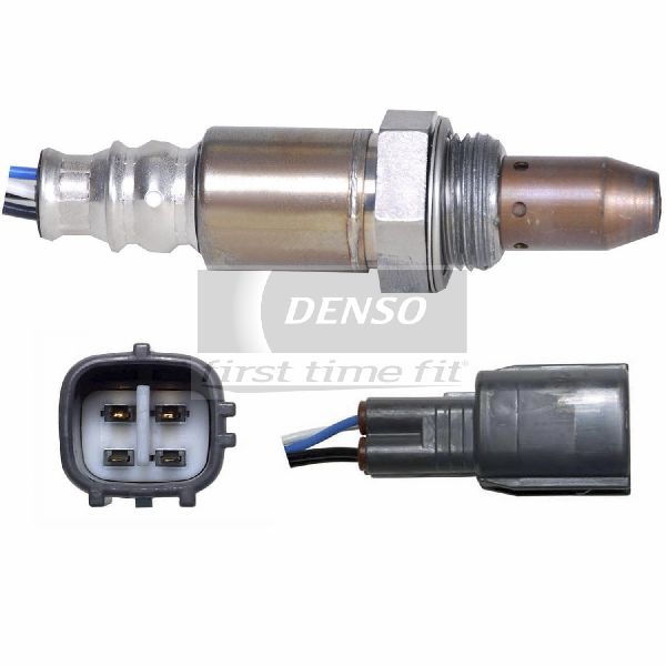
This code almost always means the front Air/Fuel Ratio sensor on the rear cylinder bank (Bank 1) has failed. The sensor is not sending any signal to the engine computer. Replacing the Bank 1, Sensor 1 A/F sensor is the most common fix. Access to this sensor, located near the firewall, is tight but manageable for a DIYer.
- P0134 on your RAV4 V6 points directly to the upstream Air/Fuel Ratio sensor on the rear cylinder bank (Bank 1).
- The most probable cause is a failed sensor, which is a standard wear-and-tear part. A related code, P0135 for the heater circuit, often appears alongside it.
- Before replacing the sensor, perform a quick visual check of the wiring for damage and check the 'A/F HEATER' fuse.
- Accessing this sensor is tight; it's located between the engine and the firewall. A special 22mm offset oxygen sensor socket is highly recommended for DIY replacement.
- Using an OEM-quality sensor (like Denso, part number 234-9056) is strongly recommended for longevity and proper performance.
What's Unique About the 2006-2012 Toyota RAV4
For the 2GR-FE V6 engine in the RAV4, which is mounted transversely (sideways), 'Bank 1' is the cylinder bank closer to the firewall. 'Sensor 1' is the Air/Fuel Ratio sensor in the exhaust manifold, before the catalytic converter. Accessing this specific sensor can be challenging due to its location on the rear of the engine, tucked between the engine block and the firewall. While the sensor itself is a common failure item across many Toyota models, its tight placement on the V6 RAV4 is a key consideration for repair, often requiring the removal of a noise insulation cover to gain access.
Symptoms You May Notice
- Check Engine Light is on
- Decreased fuel economy
- Rough or unstable idle
- Engine hesitation during acceleration
- Failing an emissions test
- Black smoke from the exhaust in some cases
- Replacing the wrong oxygen sensor. It is critical to identify Bank 1 (rear bank, by firewall) and Sensor 1 (upstream, before the catalytic converter) correctly.
- Replacing the sensor without checking for exhaust leaks or wiring damage first.
- Confusing the upstream Air/Fuel sensor (Sensor 1) with the downstream Oxygen sensor (Sensor 2), which serves a different function (monitoring catalyst efficiency).
Most Likely Causes
- Failed Air/Fuel Ratio Sensor (Bank 1, Sensor 1) 🔴 High Probability A/F sensors are wear-and-tear items that degrade over time and with mileage. Contamination from oil or coolant can also cause premature failure. The internal heater element, which is crucial for bringing the sensor to its 1200°F+ operating temperature, can also fail, leading to inactivity.
How to confirm: Use an OBD-II scanner with live data capability. Monitor the voltage for 'A/F Sensor B1S1'. If the reading is flat, unchanging, and near 3.3V while the engine is running and warmed up (even when revving), the sensor is inactive. A healthy sensor's voltage should fluctuate rapidly, dropping below 2.8V on acceleration and rising above 4.0V on deceleration.
Typical fix: Replace the Bank 1, Sensor 1 Air/Fuel Ratio sensor. The sensor is located on the rear exhaust manifold, near the firewall. Using a specialized 22mm offset oxygen sensor socket is highly recommended for removal and installation due to tight access.
Est. part cost: $120-$250 - Damaged Wiring or Connector 🟡 Medium Probability The wiring harness is exposed to significant heat in the engine bay, which can make it brittle over time. It can also be damaged by rodents or improper service. The connector itself can develop corrosion, leading to a poor connection.
How to confirm: Visually inspect the wiring harness and connector leading to the Bank 1, Sensor 1 A/F sensor. Look for any signs of melting, chafing, corrosion, or broken wires. Unplug the connector and check the pins for corrosion or damage. A multimeter can be used to check for continuity between the sensor connector and the ECM pins.
Typical fix: Repair the damaged section of the wiring harness or replace the connector pigtail. Clean any corrosion from the connector pins.
Est. part cost: $15-$50 - Blown A/F Heater Fuse ⚪ Low Probability
How to confirm: The A/F sensor has an internal heater to bring it to operating temperature quickly. This heater is on a fused circuit. Check the fuse box in the engine bay for a fuse labeled 'A/F HEATER' or similar (e.g., a 20A 'A/F' fuse). If the fuse is blown, the sensor will not operate correctly.
Typical fix: Replace the blown fuse. If the fuse blows again immediately, it indicates a short circuit in the heater element of the A/F sensor itself or its wiring, which will require further diagnosis. This often points back to a faulty sensor.
Est. part cost: $1-$5 - Exhaust Leak ⚪ Low Probability Gaskets on the exhaust manifold can fail over time, causing leaks. A leak before the sensor can introduce outside oxygen, which can confuse the sensor and, in some cases, prevent it from generating a proper signal.
How to confirm: Listen for a ticking or puffing sound from the engine bay, especially when the engine is cold. You may also see black soot marks around the exhaust manifold flange or gasket.
Typical fix: Replace the leaking exhaust manifold gasket.
Est. part cost: $20-$60
Rare But Worth Checking
- Faulty Engine Control Module (ECM): This is extremely rare and should only be considered after all other possibilities (sensor, wiring, fuses, exhaust leaks) have been thoroughly ruled out. A forum user reported replacing the sensor twice with no fix, pointing toward a potential circuit or ECM issue.
Diagnosis Steps
- Connect an OBD-II scanner to confirm the P0134 code and check for any other pending or active codes, such as P0135.
- Using the scanner's live data function, observe the signal from 'A/F Sensor B1S1'. A healthy sensor will show fluctuating voltage or current readings when the engine is running and warmed up. A flat, unchanging reading confirms the 'no activity' fault.
- Visually inspect the wiring harness and connector for the Bank 1, Sensor 1 A/F sensor. It is located on the rear exhaust manifold. Look for any signs of melting, corrosion, or physical damage.
- Locate and inspect the 'A/F' fuse (20A) in the engine bay fuse box. If it is blown, replace it and see if the code returns. If it blows again, the sensor is likely shorted internally.
- Check for exhaust leaks between the cylinder head and the A/F sensor. Listen for audible ticking noises and look for soot trails.
- If the wiring, fuse, and exhaust system are all confirmed to be in good condition, the A/F sensor itself is faulty and should be replaced.
- After replacement, clear the codes with the scanner and perform a test drive to ensure the issue is resolved. It is also recommended to perform a fuel trim reset.
Parts You'll Likely Need
- Air/Fuel Ratio Sensor (Bank 1, Sensor 1)
(OEM #89467-48050)— This is the primary component responsible for the signal the ECM is missing. It is a common wear item that fails with age and mileage.
Trusted brands: Denso (OEM supplier), NTK
OEM price range: $180-$250
Aftermarket price range: $120-$180
Related Codes That Often Appear With This One
- P0135: O2 Sensor Heater Circuit Malfunction (Bank 1 Sensor 1) - This code often accompanies P0134 as a failure of the internal heater element is a primary reason for the sensor's inactivity.
Platform-Specific Known Issues
- Difficult Access to Bank 1 Sensor 1: The Bank 1 Sensor 1 is located on the rear exhaust manifold, between the engine and the firewall. Access is very tight. Technicians often access it from the top of the engine bay. Removing a plastic noise insulation cover attached to the engine may be required to gain clearance. Using a 22mm (or 7/8") offset oxygen sensor socket with a long extension and a universal joint is highly recommended to reach and get leverage on the sensor.
Mechanic-Grade Diagnostic Values
- A/F Sensor Heater Resistance — expected: 1.8 to 3.4 Ω at 20°C (68°F). Failure: An open circuit (infinite resistance) or a reading outside this range indicates a faulty heater element.
- A/F Sensor Insulation Resistance — expected: 10 kΩ or higher. Failure: A low resistance reading indicates an internal short between the heater and sensor elements.
- KOEO Voltage at Harness (Sensor Unplugged) — expected: 3.0V on signal wire (A1A-) and 3.3V on signal wire (A1A+). Failure: Missing or incorrect voltages point to a problem with the ECM or the wiring between the ECM and the sensor connector.
- Live Data Voltage (A/FS B1 S1) — expected: Should fluctuate rapidly. Drops below 2.8V on hard acceleration, rises above 4.0V on deceleration (fuel cut).. Failure: A static, flat-line voltage reading (often stuck near 3.3V) indicates no activity.
Hidden / Shadow Codes Worth Checking
- P0135: O2 Sensor Heater Circuit Malfunction (Bank 1 Sensor 1). This code is very specific to the heater element inside the sensor and is a primary cause of the 'no activity' P0134 code. (see via Standard OBD-II scanner.)
- P2238 / P2239: A/F Sensor Pumping Current Circuit Low / High (Bank 1 Sensor 1). These are more specific circuit codes that can pinpoint whether the issue is an open or a short in the sensor's signal circuit, often seen on professional scan tools. (see via Professional scan tool like Toyota Techstream.)
Scan Tool Commands That Help
- Toyota Techstream: Active Test: A/F CONTROL — Use this to verify if the sensor is capable of responding. The test allows you to manually command a rich (+25%) or lean (-12.5%) fuel mixture and watch the A/F sensor voltage on the live data screen. A good sensor will react almost immediately to the commanded change.
- OBD-II Scanner or Techstream: Clear DTCs / Reset Memory — After replacing the A/F sensor, it's critical to clear the stored trouble codes. This also resets the learned long-term fuel trim values, allowing the ECM to create a new fuel map based on the accurate readings from the new sensor.
Wiring & Ground Locations
- B1S1 ECM Pins — On the Engine Control Module (ECM), located in the left side of the engine compartment.. For circuit testing, the Bank 1 Sensor 1 wires connect to ECM connector B30 at pins: 86 (HA1A - Heater), 93 (A1A+ - Signal +), and 116 (A1A- - Signal -). This allows for checking continuity from the sensor plug to the ECM.
- Engine Harness Ground (Rear) — A primary engine harness ground point attaches to the side of the rear cylinder head, directly underneath the throttle body.. A poor connection at this ground point can cause erratic or missing signals from sensors on the rear bank of the engine, including the Bank 1 A/F sensor.
- Valve Cover Grounds — The 2GR-FE uses ground straps that connect from the valve covers to the chassis, often near the strut towers.. These are major engine-to-body grounds. Corrosion or a loose connection here can cause a variety of sensor and drivability issues, including phantom sensor codes.
Real Owner Repair Stories
- IH8MUD.com forum user (2004 Toyota 100-Series Land Cruiser (different model, but same code behavior)) — P0134 code would only appear during long highway trips, after about 75 miles. No other performance issues were noted.
❌ Tried (didn't work) Clearing the code would work temporarily, but it would return under the same highway driving conditions.
✅ What actually fixed it The final fix was not posted, but the immediate diagnostic advice from other experienced users was to swap the Bank 1 and Bank 2 A/F sensors to see if the fault code changed to P0154 (Bank 2). This would confirm an intermittent failure within the sensor itself, rather than a wiring issue. - ToyotaNation.com forum user (High-mileage (351k miles) Toyota) — Persistent P0134 code with slightly reduced fuel economy. Live data showed no activity from the sensor.
❌ Tried (didn't work) Replacing the Bank 1 Sensor 1 with a new OEM sensor did not fix the problem. The EFI relay was also checked and found to be good.
✅ What actually fixed it The thread documents an ongoing diagnosis, highlighting that after a new sensor fails to resolve the code, the next step is a full circuit diagnosis, checking for an open or short in the harness between the sensor connector and the ECM. This story serves as a critical reminder that while the sensor is the most likely cause, it is not the only cause.
OEM Part Supersession History
89467-08010→89467-48050— Standard part revision by the manufacturer.
Diagnostic Flowchart
Other Known Issues on This Vehicle
Issues unrelated to this code that are worth knowing about as an owner of this generation:
- VVT-i Oil Line Rupture 🔴 High — Common on early models (2006-2009) that have not had the updated part installed. Can lead to catastrophic engine failure from rapid oil loss. (Ref: Limited Service Campaign (LSC-90K) was issued. The original rubber hose section is replaced with an all-metal line (P/N 15772-31030).)
- Water Pump Failure 🟠 Medium — Known to fail prematurely, sometimes as early as 60,000-80,000 miles, but more commonly around 120,000 miles. Symptoms include a growling noise, or pink/white crusty residue from a coolant leak at the weep hole.
- Steering Intermediate Shaft Clunk 🟡 Low — A clunking or popping noise may be heard from the steering column when turning at low speeds. Common on 2006-2008 models. (Ref: T-SB-0318-08 provides a procedure to replace the shaft with an improved part.)
- Idler Pulley Noise 🟡 Low — The No. 2 idler pulley bearing can fail, causing a whining or grinding noise from the serpentine belt area. (Ref: T-SB for 2GR-FE No. 2 Idler Pulley Noise (e.g., on other models) exists, though not specific to P0134.)
Used vs. New Parts: Buying Guide for This Vehicle
When a used part is the smart pick: A used part is generally NOT recommended for the Air/Fuel sensor itself, as it is a wear item with a finite lifespan. However, sourcing a used wiring harness connector pigtail from a junkyard is a smart choice if your original connector is melted or damaged.
Donor-vehicle mileage cap: roughly under 80000 miles for the part to have meaningful remaining life.
What to inspect on the donor part:
- For a connector pigtail, ensure the plastic is not brittle or cracked.
- Check that the locking tab is intact and functional.
- Inspect the wire insulation for at least 6 inches back from the connector, ensuring it's not heat-damaged, stiff, or frayed.
- Look for clean, corrosion-free pins inside the connector.
OEM-only on this vehicle (don't cheap out):
- Air/Fuel Ratio Sensor
Aftermarket brands forum-validated for this vehicle:
- Denso (is the OEM supplier, this is the best choice after the Toyota-branded part)
- NTK (NGK)
Brands owners have reported issues with on this vehicle:
- Unbranded, 'white-box' sensors from online marketplaces are frequently reported to be incompatible, fail quickly, or be dead-on-arrival.
Real Owner Stories
Aggregated from forums and TSBs cited above. Mileages and costs reflect what owners reported in those sources.
2006-2012 Toyota RAV4 2GR-FE 3.5L V6
Symptoms: The owner experienced the P0134 code appearing intermittently, specifically during long highway trips rather than during city driving.
What fixed it: The diagnosis suggested the failure was not immediate but occurred under specific operating conditions, requiring a check of the full circuit.
Source hint: ih8mud.com - 'Code P0134 on highway trips'
2006-2012 Toyota RAV4 2GR-FE 3.5L V6
Symptoms: The owner performed extensive troubleshooting for a P0134 code that persisted even after considering a simple sensor swap.
What fixed it: The owner highlighted the necessity of diagnosing the entire circuit rather than just replacing the sensor.
Source hint: toyotanation.com - 'Making Progress: P0134 Diagnosis Questions'
2006-2012 Toyota RAV4 2GR-FE 3.5L V6
Symptoms: Difficulty accessing the Bank 1 Sensor 1 due to its location on the firewall side of the engine.
What fixed it: Removal of other components for clearance and using an offset oxygen sensor socket to reach the rear manifold.
Source hint: rav4world.com forum discussions
Related OBD-II Codes
Frequently Asked Questions
Where is the Bank 1 Sensor 1 located on my RAV4 3.5L V6?
What tools do I need to replace the A/F sensor on the 2GR-FE engine?
Is there a specific fuse I should check for a P0134 code on this vehicle?
My RAV4 is showing P0134; could this be related to the VVT-i oil line issue?
What should the voltage readings look like for a healthy A/F Sensor B1S1 on a RAV4 V6?
Can an exhaust leak cause a P0134 code on the 2GR-FE?
Helpful Videos

We Have This Part in Stock


The information in this article is provided for general reference and educational purposes only. Vehicle specifications, procedures, and part compatibility can vary by production date, trim level, and region. Always consult your vehicle's factory service manual and verify part numbers before purchasing or performing repairs. Safety-critical components such as airbags, seat belts, and braking systems should be installed by a qualified professional.
- Toyota RAV4:
- 🎬 Helpful Videos
- 🛍️ Shop This Part
- What's Unique About the 2006-2012 Toyota RAV4
- Symptoms You May Notice
- Most Likely Causes
- Rare But Worth Checking
- Diagnosis Steps
- Parts You'll Likely Need
- Related Codes That Often Appear With This One
- Platform-Specific Known Issues
- Mechanic-Grade Diagnostic Values
- Hidden / Shadow Codes Worth Checking
- Scan Tool Commands That Help
- Wiring & Ground Locations
- Real Owner Repair Stories
- OEM Part Supersession History
- Diagnostic Flowchart
- Other Known Issues on This Vehicle
- Used vs. New Parts: Buying Guide for This Vehicle
- Real Owner Stories
- 2006-2012 Toyota RAV4 2GR-FE 3.5L V6
- 2006-2012 Toyota RAV4 2GR-FE 3.5L V6
- 2006-2012 Toyota RAV4 2GR-FE 3.5L V6
- Related OBD-II Codes
- Frequently Asked Questions
- 🎟️ Get 5% Off