

U1002 on 2005-2012 Nissan Maxima: Causes and Fixes for CAN Communication Loss
Code U1002 on a 2005-2012 Nissan Maxima means there's a loss of communication between electronic control modules. The most common causes are poor electrical grounds, a weak battery, or a wiring issue, often implicating the ABS module or IPDM. Diagnosing this code is complex and usually requires professional service.
- U1002 is a network communication code, not a specific part failure.
- Always start diagnosis by checking the battery and all major ground connections, as these are common and inexpensive fixes.
- This code is difficult to diagnose at home and usually requires professional help due to the need for specialized tools and schematics.
- Do not replace expensive control modules unless power, ground, and the CAN wiring have been thoroughly tested and confirmed to be good.
What's Unique About the 2005-2012 Nissan MAXIMA

The 2005-2012 Maxima spans two generations (6th and 7th), both of which rely heavily on CAN communication for all vehicle functions. Like many Nissans from this era, they can be susceptible to electrical issues stemming from corroded ground points and harness problems. A particularly common failure point is the ECM ground connection. Unlike a simple sensor code, U1002 doesn't point to a single part but rather to a system-wide communication failure, making diagnosis a process of elimination. 🎬 Watch: A step-by-step walkthrough for fixing Nissan CAN communication codes. A faulty Intelligent Power Distribution Module (IPDM) or ABS actuator are also known culprits on these platforms.
Diagnostic Flowchart

Tap your situation to follow the diagnostic path that matches what you're seeing on this vehicle.
Generation note: This guide covers the end of the 6th generation (2005-2008, A34) and the beginning of the 7th generation (2009-2012, A35) Nissan Maxima. While the underlying CAN architecture is similar, module locations and wiring harness routing differ. For example, on some earlier models, the TCM and ECM may be located behind the glove box, while on others, they are in different locations. The Intelligent Power Distribution Module (IPDM), a common source of electrical issues, also varies between generations. Always refer to the specific service manual for your model year.
Symptoms You May Notice

- Check Engine Light is on
- Vehicle will not start, or starts only with the remote starter
- ABS, VDC, or SLIP warning lights are illuminated
- Transmission may be stuck in one gear (limp mode) or shift erratically
- Gauges on the instrument cluster behave erratically or don't work
- Power windows, locks, or HVAC system may not function correctly
- Engine may stall unexpectedly while driving
- Cruise control may not work and the 'Set' light may flash
- Replacing a control module without first verifying its power, ground, and the integrity of the CAN wiring. The module itself is often not the root cause.
- Overlooking corroded ground connections, which are a very common and inexpensive fix for this code on Nissans.
Most Likely Causes

- Poor Ground Connections 🔴 High Probability Nissan vehicles of this era are known for issues with corrosion at key grounding points, which can cause a voltage drop and disrupt module communication. The main ECM grounds, often located under the dash or on the engine block, are a frequent source of the problem.
How to confirm: Visually inspect and test the main ground straps from the battery to the chassis 🎬 Watch: How to replace a corroded Nissan battery ground cable. and from the chassis to the engine block. Use a multimeter to check for voltage drops between the negative battery terminal and the module's ground pin. A reading of even 0.2 ohms on a critical ground can be enough to cause issues.
Typical fix: Clean all corrosion from the ground points, mating surfaces, and bolts with a wire brush and ensure the connections are tight. In some cases, owners have run a new, redundant ground wire from the ECM bracket to a clean chassis point to create a more robust connection.
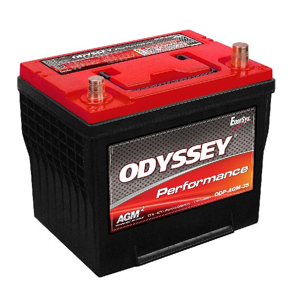
Est. part cost: $5-$30 - Low Battery Voltage or Weak Battery 🟡 Medium Probability Control modules are sensitive to voltage. If the battery voltage drops below a certain threshold (e.g., 10V) during startup or operation, modules can stop communicating and set U-codes. This is a common trigger for CAN communication faults across many Nissan models.
How to confirm: Test the battery with a load tester. A simple voltage check is not enough. The battery should hold its charge under load. Also, check the alternator's output to ensure it's properly charging the battery (typically 13.2-14.8V).
Typical fix: Recharge or replace the vehicle's battery. Clean the battery terminals and cable ends.
Est. part cost: $150-$250 - Damaged Wiring Harness or Connectors 🟡 Medium Probability Wiring for the CAN bus can become chafed, corroded, or damaged over time, especially in the engine bay or under the vehicle. Flood damage is a major cause of such issues. Connectors can also have pins back out or become bent, causing intermittent connections.
How to confirm: This requires a visual inspection of the harness and testing the CAN High and CAN Low wires for continuity, shorts to power, or shorts to ground using a multimeter. The resistance between CAN High and CAN Low at the DLC should be approximately 60 ohms with the battery disconnected. A reading of 120 ohms suggests an open circuit or a problem with a terminating module (like the ECM or IPDM).
Typical fix: Repair the damaged section of the wiring harness. This may involve soldering broken wires, replacing corroded pins, or replacing an entire harness section if the damage is severe.
Est. part cost: $20-$1000+ - Failed Control Module (ABS, IPDM, ECM) ⚪ Low Probability An internal failure in a module (like the ECM, TCM, BCM, or ABS actuator) can cause it to stop communicating or, in some cases, broadcast noise that disrupts the entire network. The ABS actuator and the Intelligent Power Distribution Module (IPDM) are particularly noted as potential failure points that can set a U1002 code.
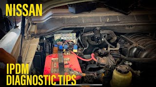
How to confirm: This is typically the last step after confirming power, ground, and wiring are all good. A technician will use a scan tool to see which module is offline and may try to disconnect modules one by one to see if communication is restored to the others. The IPDM has a self-test function that can be initiated to check its outputs. 🎬 See this guide for IPDM and engine relay diagnostic tips.
Typical fix: Replace the faulty module. The new module will often require programming by a Nissan dealer or a qualified shop with the proper tools. An IPDM with a matching part number may not require programming.
Est. part cost: $200-$1600+
Rare But Worth Checking
- Blown Fuse: A fuse that powers a critical control module can cause it to drop off the network. High-level fuses like 'Ignition 1' or 'Elec B' power multiple modules and should be checked. A blown fuse for the AWD module has been shown to cause U-codes on related platforms.
- Aftermarket Accessories: Improperly installed remote starters, alarms, or audio equipment can interfere with the CAN network and cause communication codes.
- Faulty Intelligent Power Distribution Module (IPDM): The IPDM is more than a fuse box; it's a control module that can fail internally, causing a wide range of electrical issues, including CAN communication faults. Symptoms can include a crank-no-start condition or erratic accessory operation. In some cases, a faulty ECM relay within the IPDM is the specific cause.
Diagnosis Steps
- Check for and prioritize any other communication codes (U1000, U1001, U01xx) as they can help identify the source of the problem.
- Fully charge and load test the battery. Ensure battery terminals are clean and tight. Low voltage is a common cause of CAN codes.
- Inspect all main power and ground connections for the engine, body, and battery. Pay special attention to the ECM grounds under the dash and the main ground points in the engine bay. Clean any corrosion and tighten all bolts.
- Using a multimeter, check for 60 ohms of resistance across pins 6 (CAN-H) and 14 (CAN-L) at the Data Link Connector (DLC) with the battery disconnected. A reading of 120 ohms suggests an open circuit or a problem with a terminating resistor in a module like the ECM or IPDM.
- If resistance is incorrect, inspect the CAN wiring harness for visible damage, chafing, or corrosion, paying close attention to harness connectors and splices.
- Check fuses related to control modules, particularly high-level fuses in the IPDM that power multiple systems.
- If wiring, grounds, and power are confirmed to be good, the issue may be an internal fault in one of the control modules. This requires advanced diagnostics, often by disconnecting modules one by one to isolate the faulty unit. The ABS module is a common point of failure.
Parts You'll Likely Need
- Battery
- Intelligent Power Distribution Module (IPDM)
- ABS Control Module / Actuator
- Engine Control Module (ECM)
- ECM Relay
Related Codes That Often Appear With This One
- U1000 — U1000 is the general CAN communication failure code. U1002 is a more specific version of the same fault with a tighter timing requirement.
- U1001 — This code specifically points to a loss of communication with the Engine Control Module (ECM).
- U01xx (e.g., U0101, U0121) — These are standardized codes indicating a loss of communication with a specific module (e.g., U0101 for TCM, U0121 for ABS Control Module). They help pinpoint which module is offline.
- C1110, C1111 — These codes indicate an internal controller failure or ABS motor electrical failure within the ABS module, a common cause of network-wide communication issues on these vehicles.
Technical Service Bulletins (TSBs) & Recalls
- NTB10-066A / NTB10-066B: Provides diagnostic guidelines for CAN codes U1000, U1001, U1002, and U1010. It confirms U1002 has a tighter timing spec than U1000 and stresses diagnosing communication codes first.
- NTB13-027C: A diagnostic flowchart for CAN communication issues, providing helpful tips like checking for low voltage, inspecting high-level fuses, and confirming power/ground at modules before replacement.
- NTB10-145B: Specifically addresses diagnosing the ABS/VDC system when a U1000 code is present, advising against replacing the actuator without full diagnosis.
Platform-Specific Known Issues
- ECM Grounding Under Dash: On the 6th generation Maxima, the ground connections for the ECM are located under the dashboard and secured to a cross brace. These grounds (often labeled M14 and M78 in service manuals) can become loose or develop high resistance, leading directly to U1000/U1002 codes. Technicians and owners have reported success by removing, cleaning, and tightening these grounds, or even splicing in a new ground wire to a more reliable chassis point.
- IPDM Failure and Self-Test: The Intelligent Power Distribution Module (IPDM), located in the engine bay, is a known weak point. It contains non-serviceable internal relays that can fail, causing loss of power to critical modules like the ECM or fuel pump. A failing IPDM can cause a U1002 code along with a crank-no-start condition. Many Nissan vehicles have a built-in IPDM self-test that can be activated to check its functionality by cycling various components like wipers and headlights.
Mechanic-Grade Diagnostic Values
- CAN Bus Resistance — expected: ~60 Ω across DLC pins 6 (CAN-H) and 14 (CAN-L) with battery disconnected.. Failure: 120 Ω indicates an open in the circuit or an issue with one of the two terminating resistors. Near 0 Ω indicates a short between the CAN High and Low lines.
- CAN Bus Voltage (Recessive State) — expected: Both CAN-H and CAN-L should be at ~2.5V.. Failure: Significant deviation from 2.5V on either line when the bus should be idle.
- CAN Bus Voltage (Dominant State) — expected: CAN-H rises to ~3.5V, CAN-L drops to ~1.5V.. Failure: Voltages that do not reach these levels, or a voltage of 1.4V or less, can indicate a failure in a module's CAN transceiver.
- Terminating Module Resistance — expected: ~120 Ω. Failure: An open or short reading when measuring resistance directly at a known terminating module (like the ECM or IPDM) with it disconnected from the harness.
Scan Tool Commands That Help
- Manual Procedure (No Scan Tool): IPDM E/R Auto Active Test (Self-Test) — To verify that the IPDM can command various body electrical components (wipers, lights, A/C clutch, etc.), confirming the IPDM's basic functions are operational. To activate: Ignition ON, press driver's door switch 10 times in 20 seconds, Ignition OFF, then Ignition ON again. A horn chirp confirms activation.
- Nissan CONSULT-III: CAN Diag Support Monitor / V-CAN Diagram — To get a visual overview of the entire CAN network's status. The tool polls all modules and color-codes them based on communication status (e.g., Green for OK, Red for current fault), which quickly identifies which modules are offline or reporting errors.
- Nissan CONSULT-III: Self-Diagnosis — To pull DTCs from a specific control unit that is still communicating. This helps narrow down if a module is reporting a fault or simply not responding at all.
Wiring & Ground Locations

- ECM (Engine Control Module) — Located behind the glove box assembly.. The ECM is a terminating module for the CAN bus. A bad ground to the ECM can disrupt the entire network. Its main ground is a black wire grounded behind the right side of the dash.
- ABS Actuator & Electric Unit — Located in the engine bay, underneath the brake master cylinder. Access typically requires removing the engine air intake assembly.. A common point of failure that can bring down CAN communication. The main connector has specific power and ground pins (Pins 1 and 4 are grounds) that must be verified before condemning the unit.
- IPDM E/R (Intelligent Power Distribution Module Engine Room) — Black box located in the engine compartment, usually near the battery.. The IPDM is a central hub for power and communication. It's a terminating module and contains the critical ECM power relay.
- Main Engine/Transmission Grounds — Key locations include a strap from the intake manifold to the battery area, another from the cylinder head to the firewall, and a transmission-to-chassis ground.. Corrosion or looseness at any of these primary ground points can introduce electrical noise and voltage drops, causing communication codes.
Real Owner Repair Stories
- YouTube channel 'ADVANCED LEVEL AUTO' (2011 Nissan Maxima 3.5L V6) — No crank, no start, no communication with the ECM. Cooling fans running constantly with ignition on. Multiple modules reporting U1000 CAN communication codes.
❌ Tried (didn't work) Initial scan tool connection failed to communicate with the engine module.
✅ What actually fixed it A single blown 15-amp fuse in the IPDM was found. Replacing the fuse immediately shut off the fans, restored communication with the ECM, and allowed the vehicle to start. - Maxima.org forum user (2019 Nissan Maxima (8th Gen, but relevant principle)) — No start condition after battery died and was reconnected. Multiple communication codes present.
❌ Tried (didn't work) Initial diagnosis was unclear due to the number of codes.
✅ What actually fixed it The investigation found an incorrect IPDM from a Nissan Altima had been installed. The final fix required replacing the incorrect IPDM with the correct part number for the Maxima, replacing a faulty ECM, and programming both new modules. A bad starter was also discovered and replaced.
OEM Part Supersession History
White-colored IPDM housing→Black-colored IPDM housing— Nissan updated the IPDM assembly. The black housing indicates it is the newer, revised part.
Heads up: While the color indicates the revision, the specific part number on the module must still match the vehicle's options and model year for full compatibility.N/A (Original ECM Relay in IPDM)→284B7-CW29E— This is the genuine Nissan OEM part number for the serviceable 4-prong ECM relay located inside the IPDM, which is a very common failure point causing no-start and communication issues.
Model Year Variations Within This Range
- 2005-2012: On vehicles equipped WITH Traction Control (TCS), the ABS control module is located separately from the actuator, typically under the driver's side dash. Diagnostic checks should reference connector E91. On vehicles WITHOUT TCS, the control unit is integrated with the actuator in the engine bay, and diagnostics use connector E9.
Helpful Videos
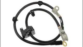

Used OEM Parts in Stock



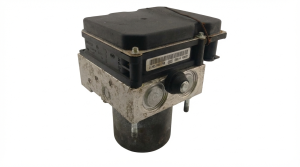
New Aftermarket Parts Available

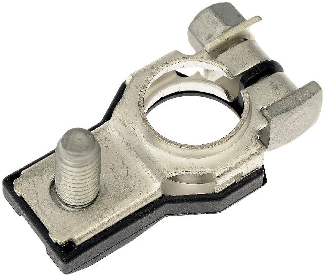
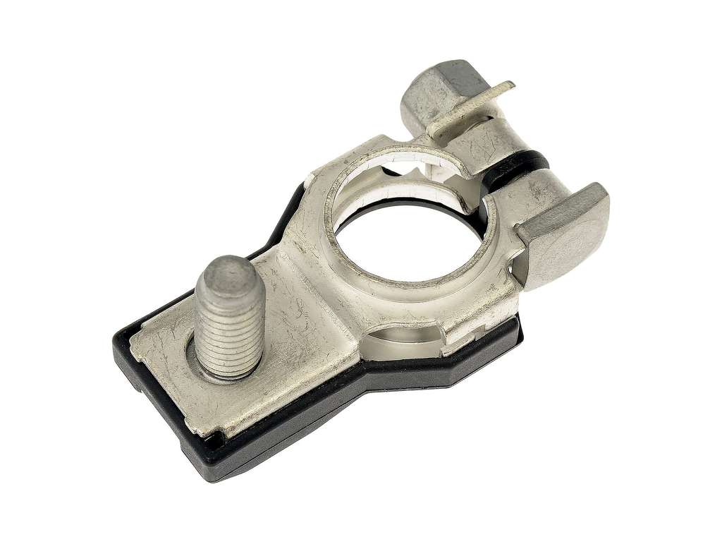

The information in this article is provided for general reference and educational purposes only. Vehicle specifications, procedures, and part compatibility can vary by production date, trim level, and region. Always consult your vehicle's factory service manual and verify part numbers before purchasing or performing repairs. Safety-critical components such as airbags, seat belts, and braking systems should be installed by a qualified professional.
- Nissan MAXIMA:
- 🎬 Helpful Videos
- 🛍️ Shop This Part
- What's Unique About the 2005-2012 Nissan MAXIMA
- Diagnostic Flowchart
- Symptoms You May Notice
- Most Likely Causes
- Rare But Worth Checking
- Diagnosis Steps
- Parts You'll Likely Need
- Related Codes That Often Appear With This One
- Technical Service Bulletins (TSBs) & Recalls
- Platform-Specific Known Issues
- Mechanic-Grade Diagnostic Values
- Scan Tool Commands That Help
- Wiring & Ground Locations
- Real Owner Repair Stories
- OEM Part Supersession History
- Model Year Variations Within This Range
- 🎟️ Get 5% Off