

U0269 on 2013-2018 Cadillac ATS: Lost Communication With Side Object Detection Module B
U0269 indicates a communication failure with the passenger side blind spot monitoring module. This is most often caused by a failed module due to water intrusion or a damaged wiring harness in the rear bumper. Expect a repair cost of $400-$800, as the replacement module requires professional programming.
- U0269 specifically points to a communication problem with the passenger side blind spot radar sensor.
- The most likely cause is a failed sensor module due to water damage, given its location in the rear bumper.
- This is not a simple DIY part swap; the replacement module must be programmed by a professional with the correct software.
- Before replacing the module, it's crucial to inspect the wiring harness for damage, as this could be a cheaper fix.
- A warning message for the blind spot system should be addressed, as a failing module can sometimes cause broader electrical issues on the vehicle's data network.
What's Unique About the 2013-2018 Cadillac ATS
On the Cadillac ATS, the side object detection modules are mounted in the corners of the rear bumper fascia, making them highly susceptible to moisture, road salt, and physical damage from minor impacts. This exposure is a leading cause of premature failure, with water often entering through cracks in the module's housing or compromised seals. Additionally, a specific GM Technical Service Bulletin (TSB PIT5441C) notes that this code can sometimes be falsely triggered by a faulty dealership diagnostic tool (MDI cable) during a scan, which can mislead technicians by creating false communication codes on the object detection bus (DLC pins 3 and 11).
Diagnostic Flowchart
Tap your situation to follow the diagnostic path that matches what you're seeing on this vehicle.
Symptoms You May Notice
- "Service Side Blind Zone Alert System" message on the Driver Information Center (DIC).
- Warning light on the dashboard.
- Passenger side blind spot indicator light in the mirror may stay on dimly or not light up at all.
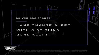
- Blind spot monitoring and rear cross-traffic alert systems are disabled and unavailable for use. 🎬 Watch: How the side blind zone alert system should work
- In some cases, a failing module can cause interference on the data network, leading to seemingly unrelated issues with the radio or phone connectivity.
- Replacing the module without checking the wiring first. A simple wiring repair could save hundreds of dollars.
- Ignoring the code. A failing module can sometimes cause other issues on the CAN bus network, potentially leading to battery drain or problems with other electronic systems like the radio.
Most Likely Causes
- Failed Passenger Side Object Detection Module 🔴 High Probability The module is located in the rear bumper corner, where it is exposed to water, salt, and debris kicked up by the rear tires. The plastic housing can develop cracks from minor impacts or stress, allowing moisture to penetrate and corrode the internal circuit board. In salt-belt regions, this is an extremely common failure.
How to confirm: After confirming power, ground, and CAN bus signals at the module connector, the module itself is the likely culprit. A professional scan tool may show the module as 'offline'. Visually, the module case may appear swollen or cracked, and unplugging the connector may reveal water or corrosion.
Typical fix: Replace the passenger side object detection module and perform the required programming and calibration procedure with a GM-compatible scan tool. Sealing the new module's seams with a quality automotive sealant before installation is a recommended preventative measure.
Est. part cost: $200-$450 - Damaged Wiring or Connector 🟡 Medium Probability The wiring harness runs through the rear bumper area and can be damaged in a minor rear-end collision or from road debris. The connector pins can also corrode due to water intrusion, sometimes from water running out of a failed module's connector.
How to confirm: Visually inspect the wiring harness leading to the passenger side module for any cuts, abrasions, or pinch points. Unplug the connector and check for green or white corrosion, moisture, or bent/broken pins.
Typical fix: Repair the damaged section of the wiring harness or replace the connector pigtail. In severe cases of corrosion, the entire rear bumper harness may need replacement. Ensure the connection is sealed with dielectric grease against moisture.
Est. part cost: $20-$150 - Improper Module Mounting ⚪ Low Probability The modules are mounted on brackets that are heat-staked to the bumper fascia. A previous repair or impact can break these mounts, causing the module to be misaligned or vibrate excessively, which can lead to communication issues or internal damage over time.
How to confirm: Remove the rear bumper fascia and inspect the module's mounting brackets. Check for broken heat stakes, loose zip ties from a previous improper repair, or any signs of previous, improper repairs.
Typical fix: Repair the mounting bracket using a plastic welding kit or replace the rear bumper fascia if the mounting points are not salvageable. Ensure the module is securely mounted and properly aimed. Note that after correcting the mount, the module may need to be replaced and programmed to clear the fault immediately.
Est. part cost: $50-$1000+
Rare But Worth Checking
- Faulty Diagnostic Tool (MDI Cable): As per TSB #PIT5441C, the code can be falsely set by the technician's own diagnostic equipment. The bulletin advises technicians to test their MDI cable on a known-good vehicle if this code appears unexpectedly during diagnosis, as a fault in the cable can disrupt communication on the object detection bus pins (3 and 11) of the DLC.
- Faulty Active Safety Control Module: In rare cases, the main control module that communicates with all the safety sensors can fail, but this would typically set multiple communication codes for other sensors as well (e.g., front camera, long-range radar).
Diagnosis Steps
- Scan all vehicle modules with a professional-grade scan tool capable of reading GM-specific 'U' codes.
- Note if U0269 is current or history. Attempt to clear the code and see if it returns immediately.
- Gain access to the passenger side rear bumper area. This requires partial or full removal of the rear bumper fascia. A YouTube video by user 'emoappropriate' shows this process on an ATS.
- Visually inspect the wiring harness and connector for the Side Object Detection Module B. Look for any signs of physical damage, corrosion, or moisture. Water may run out of the connector when unplugged.
- Using a multimeter, check for proper power (11.8V-12.6V) and ground (less than 0.1 Ω resistance to chassis ground) at the module's connector (Pin 8) with the ignition on.
- If power and ground are good, check the CAN bus communication lines. With the battery disconnected, measure resistance between the two CAN wires at the connector. A reading of ~120 Ohms indicates the module's internal terminator is likely okay, but there's a break elsewhere. A reading of ~60 Ohms indicates the wiring to the rest of the network is likely intact.
- If wiring, power, and ground are all confirmed to be good, the Side Object Detection Module B is the most likely cause of failure.
- If you are a technician, consider the possibility of a faulty MDI cable as outlined in TSB PIT5441C before replacing parts.
Parts You'll Likely Need
- Side Object Detection Module (Right/Passenger Side)
(OEM #84430634)— This module is the most common failure point for code U0269 due to its vulnerable mounting location and susceptibility to moisture damage. This part number is used for both left and right sides.
Trusted brands: ACDelco, GM Genuine Parts
OEM price range: $230-$450
Aftermarket price range: $150-$300
Related Codes That Often Appear With This One
- U0268 — This is the corresponding code for 'Lost Communication With Side Object Detection Module A' (the driver's side). If both modules were damaged by water or an impact, both codes may appear together.
- U0075 — This is a general CAN bus communication code that can be set alongside U0269, as noted in TSB PIT5441C, especially when the issue is related to a faulty diagnostic tool.
Technical Service Bulletins (TSBs) & Recalls
- PIT5441C: Advises technicians that DTCs U0269, among others, can be falsely set by a faulty Multiple Diagnostic Interface (MDI) cable used for vehicle scanning, and provides steps to verify the tool's integrity by testing on a known-good vehicle.
Platform-Specific Known Issues
- GM issued a special coverage adjustment (N172097060) for other models like the 2013-2016 Chevrolet Cruze and 2014-2015 Impala for this exact issue of water intrusion into the SBZA modules, highlighting it as a known problem with this system design, though the ATS was not explicitly included.
Mechanic-Grade Diagnostic Values
- CAN Bus Network Resistance — expected: ~60 Ω. Failure: A reading of ~120 Ω indicates an open circuit or missing terminating resistor. A reading near 0 Ω indicates a short between the CAN High and Low wires.
- CAN High Voltage (to ground, ignition on) — expected: Fluctuates between 2.5V and 3.5V (multimeter average ~2.6V).. Failure: Voltage stuck high, low, or at 0V indicates a short or open.
- CAN Low Voltage (to ground, ignition on) — expected: Fluctuates between 1.5V and 2.5V (multimeter average ~2.4V).. Failure: Voltage stuck high, low, or at 0V indicates a short or open.
- Module Power Supply — expected: 11.8V - 12.6V with ignition on.. Failure: Low or no voltage indicates a problem with the power feed circuit or fuse.
- Module Ground Circuit Resistance — expected: < 0.1 Ω to a clean chassis ground point.. Failure: High resistance indicates a corroded or loose ground connection (e.g., at G401).
Hidden / Shadow Codes Worth Checking
- No DTC set, DIC message only: Per GM bulletin PIT5622B, a "Side Detection System Unavailable" message can display on the DIC at every startup *without* any DTCs being stored. This specific condition points towards a module that is physically misaligned due to a broken mounting bracket, which the module learns over time is incorrect. (see via This is a negative finding; the absence of a DTC combined with the specific DIC message is the diagnostic clue.)
Scan Tool Commands That Help
- GM GDS2: Module Programming/Setup — This function is required after replacing a Side Object Detection Module. The new module must be programmed to the vehicle's VIN and calibrated to function correctly.
- GM GDS2: Vehicle Diagnosis / Vehicle Communication Diagnostics / Network Communication Status — This is a primary diagnostic step to identify which modules are and are not communicating on each of the vehicle's CAN buses. For a U0269, the Side Object Detection Module B would show as 'Not Communicating' on its respective network.
- GM GDS2: Clear All DTCs — Used after a repair to clear fault codes from all modules and verify the fix.
Wiring & Ground Locations
- Side Object Module Connector — In the rear bumper fascia, plugged into the radar module at each corner.. This is the primary connection point for power, ground, and communication. Pin 8 is the ground wire (Black). Water intrusion and corrosion are common here.
- G401 — Near the battery well, mounted to the left rear body mount behind the left rear tire on the frame.. This is a primary rear chassis ground. A loose or corroded G401 could cause a poor ground for the entire rear bumper harness, including the object detection modules, leading to communication faults.
- X510 / X610 — Connectors for the driver (X510) and passenger (X610) side object sensor modules.. These are the direct connectors to the modules where pin-point testing for power, ground, and CAN signals should be performed.
- Active Safety Control Module — Located in the rear compartment, behind the left side trim panel.. This is the 'parent' module that is reporting the lost communication with the 'child' side object module. A fault here is rare but possible.
Real Owner Repair Stories
- YouTube user 'emoappropriate' (2018 Cadillac ATS) — Blind spot lights were on dimly all the time, 'Service Side Blind Zone Alert' message, and interference with the radio and phone connectivity.
❌ Tried (didn't work) Initial diagnosis was unclear due to multiple electronic issues.
✅ What actually fixed it The user removed the rear bumper, found a crack in the passenger side sensor housing that allowed moisture to get on the circuit board. Replacing the sensor with a used unit from eBay resolved all symptoms.
OEM Part Supersession History
23424942, 84037295→84430634— Part revision and consolidation by GM.
Heads up: Part number 84430634 is listed by some suppliers as discontinued, which may require sourcing from remaining dealer stock or the aftermarket. Other numbers like 23257304 and 23498109 have also been associated with this system on the ATS, making VIN verification with a dealer essential.
Helpful Videos
We Have This Part in Stock



The information in this article is provided for general reference and educational purposes only. Vehicle specifications, procedures, and part compatibility can vary by production date, trim level, and region. Always consult your vehicle's factory service manual and verify part numbers before purchasing or performing repairs. Safety-critical components such as airbags, seat belts, and braking systems should be installed by a qualified professional.
- Cadillac ATS:
- 🎬 Helpful Videos
- 🛍️ Shop This Part
- What's Unique About the 2013-2018 Cadillac ATS
- Diagnostic Flowchart
- Symptoms You May Notice
- Most Likely Causes
- Rare But Worth Checking
- Diagnosis Steps
- Parts You'll Likely Need
- Related Codes That Often Appear With This One
- Technical Service Bulletins (TSBs) & Recalls
- Platform-Specific Known Issues
- Mechanic-Grade Diagnostic Values
- Hidden / Shadow Codes Worth Checking
- Scan Tool Commands That Help
- Wiring & Ground Locations
- Real Owner Repair Stories
- OEM Part Supersession History
- 🎟️ Get 5% Off