

U0109 on 2006-2011 Cadillac STS: Lost Communication With Fuel Pump Control Module Fixes
On a 2006-2011 Cadillac STS, code U0109 is most often caused by a poor connection at the transmission X1 electrical connector, not a failed Fuel Pump Control Module. Inspecting and securing this connector as per GM's Technical Service Bulletin PIC4740F (superseding PIC4740E) is the most likely fix for the crank-no-start or stalling condition.
- For a 2006-2011 Cadillac STS, U0109 is most likely a wiring/connector problem, not a bad part.
- Always inspect the main transmission harness connector (X1) first, as detailed in TSB PIC4740E, before considering any part replacement.
- This code indicates a critical fault that can cause the vehicle to stall or fail to start; it should not be driven until repaired.
- The presence of other communication codes (U-codes) alongside U0109 strongly points to the common connector issue rather than an isolated FPCM failure.
What's Unique About the 2006-2011 Cadillac STS
For this generation of Cadillac STS and its platform mates, the U0109 code is strongly associated with a known wiring harness issue, not a faulty Fuel Pump Control Module. A General Motors TSB, PIC4740F (which supersedes PIC4740E), points directly to unseated pins or a poor connection at the main transmission harness connector (X1) as the root cause for a host of communication codes, including U0109. This often leads to misdiagnosis, where the FPCM or fuel pump is replaced unnecessarily when the actual problem is a simple, but sometimes hard to trace, connector fault that disrupts the entire network.
Diagnostic Flowchart
Tap your situation to follow the diagnostic path that matches what you're seeing on this vehicle.
Symptoms You May Notice
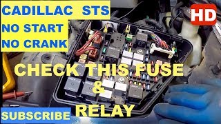
- Engine cranks but does not start. 🎬 Watch: How to check the starter fuse and relay
- Engine stalls while driving, sometimes after 30-45 minutes of running.
- Reduced engine power or 'limp mode'.
- Check Engine Light (MIL) is on.
- Multiple other warning lights may be on, such as for the traction control or 'Service StabiliTrak' message.
- Hard transmission shifting.
- Door locks may cycle while driving.
- Absence of the usual fuel pump priming sound when the key is turned to 'ON'.
- Replacing the fuel pump when the issue is a lack of command from the FPCM.
- Replacing the Fuel Pump Control Module (FPCM) before thoroughly inspecting the transmission X1 connector and related wiring harness as specified in TSB PIC4740F.
Most Likely Causes
- Loose or Corroded Transmission X1 Connector 🔴 High Probability As documented in GM Technical Service Bulletin PIC4740F, the pins within the main transmission harness connector (X1) can become loose, unseated, or suffer from fretting corrosion. This disrupts communication across the vehicle's High Speed GMLAN network for multiple modules, including the FPCM, TCM, and ABS module.
How to confirm: Visually inspect the large connector on the transmission (X1). Disconnect it and check for any backed-out pins, corrosion (which may appear as a gray film), or damage. Gently tug on each wire to ensure it is fully seated in the connector, as a side load can create a false positive lock.
Typical fix: Reseat any loose pins, clean the connector terminals with an appropriate electrical contact cleaner, and apply dielectric grease before reconnecting securely. In some cases, the connector or terminal pins may need to be replaced.
Est. part cost: $5-$25 - Damaged Wiring Harness 🟡 Medium Probability The wiring harness can be susceptible to chafing or damage, particularly near the transmission bell housing or where it is secured to the chassis. On other GM vehicles, similar issues are found where the harness rubs against the transfer case or driveshaft.
How to confirm: Perform a thorough visual inspection of the harness running to the FPCM and the main harness near the transmission. Check for continuity on the CAN bus wires (typically Tan and Tan/White) using a multimeter.
Typical fix: Repairing the damaged section of the wire or replacing the affected connector pigtail.
Est. part cost: $10-$50 - Failed Fuel Pump Control Module (FPCM) ⚪ Low Probability While the module itself can fail, it is less common than wiring or connector issues on this specific platform. The FPCM is located in the trunk on the STS, protecting it from the external corrosion seen on GM trucks where it's mounted to the frame. However, internal failure is still possible.
How to confirm: This should be the last part to suspect. All wiring, connectors, power (check FPCM fuse), and grounds to the module must be verified as good before condemning the FPCM. A bi-directional scan tool can be used to attempt to communicate directly with the module.
Typical fix: Replace the Fuel Pump Control Module. The replacement module must be programmed to the vehicle using special tools.
Est. part cost: $80-$250
Rare But Worth Checking
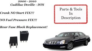
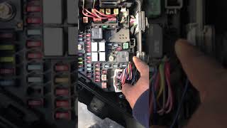
- Blown Fuse or Corroded Fuse Box Terminal: A blown fuse for the FPCM circuit will cut power and cause a communication loss. In some cases, the fuse may be intact, but the terminal in the fuse box itself becomes corroded, creating high resistance and causing an intermittent no-start or stalling condition. Always check the relevant fuses in the rear fuse block and the terminals they seat into. 🎬 See how a corroded rear fuse block causes no-starts
- Faulty ECM or other Control Module: In very rare cases, a failure within the Engine Control Module (ECM) or another module on the CAN bus can disrupt the network, but this would typically be accompanied by many other codes and symptoms.
Diagnosis Steps
- Scan all vehicle modules for stored Diagnostic Trouble Codes (DTCs). Note all communication codes (U-codes) present, as a group of them points towards a network fault.
- Check for Technical Service Bulletins (TSBs) for your vehicle's VIN. Specifically look for PIC4740F (or later revisions), which directly addresses this issue.
- Locate the transmission harness connector (X1) on the side of the transmission. Disconnect it and meticulously inspect for corrosion, moisture, or any pins that have backed out of the connector body.
- Gently pull on each wire at the back of the X1 connector to ensure they are securely crimped and seated. Repair as needed.
- If the connector looks good, inspect the wiring harness for any signs of physical damage, chafing, or melting, especially near the exhaust or where it mounts to the bell housing.
- Locate the FPCM in the trunk and check its fuse in the rear fuse block. Inspect the fuse terminals for corrosion.
- Using a wiring diagram, check for proper power and ground at the Fuel Pump Control Module connector.
- With the battery disconnected, check the resistance of the CAN bus at the diagnostic port (DLC). It should be approximately 60 ohms. An open circuit (infinite resistance) or short (0 ohms) indicates a wiring problem.
- If all wiring, connectors, and network integrity tests pass, the Fuel Pump Control Module itself may be faulty and require replacement and programming. 🎬 Watch: Professional guide to diagnosing and programming the FPCM
Parts You'll Likely Need
- Electrical Contact Cleaner & Dielectric Grease — Needed for the most common repair: cleaning and protecting the transmission X1 connector terminals.
Trusted brands: CRC, Permatex
OEM price range: $10-$25
Aftermarket price range: $10-$20 - Fuel Pump Control Module
(OEM #20877116)— This part is replaced if all wiring and connector issues have been ruled out. It is a common misdiagnosis, so ensure thorough testing is done first. Requires programming after installation.
Trusted brands: ACDelco (GM Genuine), Dorman (may come pre-programmed)
OEM price range: $150-$260
Aftermarket price range: $80-$200 - Transmission Connector (X1)
(OEM #88988938)— May be needed if the original connector housing is damaged or too corroded to be cleaned effectively.
Trusted brands: ACDelco
OEM price range: $70-$100
Aftermarket price range: $40-$70
Related Codes That Often Appear With This One
- U0100 — Lost Communication With ECM/PCM. This and other U-codes often appear with U0109 because the root cause (like the X1 connector issue) disrupts the entire vehicle communication network.
- U0101 — Lost Communication With TCM. Also directly related to the common transmission X1 connector fault.
- U0121 — Lost Communication With Anti-Lock Brake System (ABS) Control Module. Another module on the network affected by the connector issue.
- U0140 — Lost Communication With Body Control Module. Another module on the network affected by the connector issue.
- P0700 — Transmission Control Module (TCM) Requested MIL Illumination. This code is set when the TCM detects a fault (like a communication breakdown) and asks the ECM to turn on the check engine light.
Technical Service Bulletins (TSBs) & Recalls
- PIC4740F: No Crank, Multiple Warning Telltales On, Trans Shifts Hard. This is the key document for this issue. It supersedes PIC4740E and instructs technicians to inspect the transmission X1 connector terminals for a loose or poor fit as the cause for numerous communication DTCs, including U0109. It also notes to check for harness chafing near the bell housing on some models.
Platform-Specific Known Issues
- A widespread issue documented in GM TSB PIC4740F points to loose pins in the transmission X1 connector causing a loss of communication across multiple modules, triggering U0109 and many other codes simultaneously.
- Owners on forums frequently report a 'Christmas tree' effect on the dash with multiple warnings like 'Service StabiliTrak' appearing along with the U0109 code, all tracing back to the X1 connector.
Mechanic-Grade Diagnostic Values
- High-Speed GMLAN Bus Voltage (Key On, Engine Off) — expected: GMLAN-High (Pin 6 at DLC) and GMLAN-Low (Pin 14 at DLC) should both be at approximately 2.5V when at rest (recessive state). During data transmission (dominant state), GMLAN-High should go to ~3.5V and GMLAN-Low should go to ~1.5V.. Failure: Voltages stuck high or low, or no voltage, indicates a short or open on the data lines.
- High-Speed GMLAN Bus Resistance (Battery Disconnected) — expected: Approximately 60 Ohms between Pin 6 and Pin 14 at the DLC. This reading confirms the two 120-Ohm terminating resistors are present and the bus is intact.. Failure: A reading of 120 Ohms indicates one of the terminating resistors is offline (often due to a module being disconnected or an open circuit). A reading of 0 Ohms indicates a short between the GMLAN High and Low wires.
- FPCM Power Supply Voltage — expected: Battery voltage (typically 11.5V - 12.5V) should be present at the FPCM power input pin (often a Red/White wire) with the key on.. Failure: Low or no voltage indicates a problem with the fuse, relay, or wiring from the fuse block.
Scan Tool Commands That Help
- GM Tech2 / GDS2: Fuel Pump Control Module - Output Controls — After verifying power and ground to the FPCM, a bidirectional scanner like a Tech2 can be used to directly command the fuel pump on. If the pump runs with the scan tool command but not when cranking, it confirms the FPCM and pump are functional, pointing the diagnosis back towards a communication or command issue from the ECM.
- GM Tech2 / GDS2: Module Status / Communication Ping — Before diving into wiring, a technician can use the scan tool to 'ping' all modules on the network. If the FPCM, TCM, and ABS modules are all showing 'No Communication', it strongly supports the TSB's diagnosis of a network-wide failure at a central point like the X1 connector, rather than an individual module failure.
Wiring & Ground Locations
- FPCM Fuse — In the Rear Underseat Fuse Block, typically on the passenger's side. For a 2005 model, it is listed as fuse #8, controlled by relay R3.. This fuse provides the main operating power to the Fuel Pump Control Module. If it's blown or its terminals are corroded, the module cannot power on to communicate, directly causing a U0109.
- G401 — Right hand rear of the passenger compartment, under the rear seat.. This is a primary body ground point in the rear of the vehicle. The FPCM, located in the trunk, relies on a clean ground connection. A corroded or loose G401 can cause intermittent communication and power issues for the module.
- G101 — Near the left front strut tower, at the bottom of the inside fender well.. This is a key ground point for the Engine Control Module (ECM). A poor ground here can cause the ECM to malfunction and fail to communicate with other modules, including the FPCM.
- ECM Location — On the 4.6L V8, the ECM is located on the left front frame rail, below the driver's side headlamp assembly. On the 3.6L V6, it is on the passenger side valve cover.. Knowing the physical location is critical for inspecting the ECM connectors and its ground connections, which can be a rare cause of network communication faults.
Real Owner Repair Stories
- YouTube user Phillip Bailey (2007 Cadillac STS) — No start condition, multiple electrical issues.
❌ Tried (didn't work) Initial diagnosis pointed towards other components.
✅ What actually fixed it The rear fuse block (under the rear seat) was heavily corroded due to water intrusion. Replacing the corroded fuse panel resolved the no-start and communication issues. - ScannerDanner on YouTube (Cadillac (model not specified, but demonstrates a common GM issue)) — No crank, various electrical problems, low voltage readings at the underhood fuse box.
❌ Tried (didn't work) Assuming a bad positive battery cable due to voltage drop from the rear battery.
✅ What actually fixed it The main engine block ground cable was broken off where it should attach to the block. This created high resistance on the ground side of the circuit, causing the entire electrical system to malfunction under load. Re-establishing the block ground fixed the issue.
OEM Part Supersession History
20791901, 20827745, 20850927→20877116— Standard part revision and consolidation by the manufacturer.
Heads up: The replacement module (20877116) requires programming to the vehicle's VIN after installation.
Model Year Variations Within This Range
- 2005-2007 vs 2008-2011: The under-hood fuse box layout and some fuse assignments changed with the 2008 model year facelift. However, the FPCM power is supplied by the rear fuse block, which remained more consistent. Always verify the fuse diagram for the specific model year.
Helpful Videos

Used OEM Parts in Stock

New Aftermarket Parts Available

The information in this article is provided for general reference and educational purposes only. Vehicle specifications, procedures, and part compatibility can vary by production date, trim level, and region. Always consult your vehicle's factory service manual and verify part numbers before purchasing or performing repairs. Safety-critical components such as airbags, seat belts, and braking systems should be installed by a qualified professional.
- Cadillac STS:
- 🎬 Helpful Videos
- 🛍️ Shop This Part
- What's Unique About the 2006-2011 Cadillac STS
- Diagnostic Flowchart
- Symptoms You May Notice
- Most Likely Causes
- Rare But Worth Checking
- Diagnosis Steps
- Parts You'll Likely Need
- Related Codes That Often Appear With This One
- Technical Service Bulletins (TSBs) & Recalls
- Platform-Specific Known Issues
- Mechanic-Grade Diagnostic Values
- Scan Tool Commands That Help
- Wiring & Ground Locations
- Real Owner Repair Stories
- OEM Part Supersession History
- Model Year Variations Within This Range
- 🎟️ Get 5% Off