

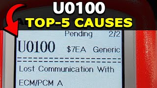
U0100 on 2008-2012 Ford Escape: Fixing 'Lost Communication with PCM' Errors
The U0100 code on a 2008-2012 Ford Escape means the main engine computer (PCM) has lost communication. This often causes a no-start or stalling. The most likely causes are a weak battery, corroded ground wires, or a faulty instrument cluster, not a bad PCM. The instrument cluster is a known weak point and often the root cause.
- U0100 on a 2008-2012 Escape is a critical code indicating a communication network failure; do not drive the vehicle.
- Always start diagnosis with the basics: test the battery and inspect all major ground connections before suspecting expensive parts.
- A dead or flickering instrument cluster accompanied by a U0100 code is a strong indicator that the cluster itself has failed, a known issue on this platform.
- Do not replace the PCM unless you have professionally verified that all power, grounds, and the CAN bus wiring are in perfect condition.
What's Unique About the 2008-2012 Ford Escape

While U0100 is a generic network code, the 2008-2012 Escape has a known weakness in its instrument panel cluster (IPC). The IPC on this platform is not just a display; it's an active computer module on the CAN bus that acts as a gateway and contains one of the network's 120-ohm terminating resistors. A failing instrument cluster due to bad internal solder joints can disrupt the entire network, causing a U0100 code along with a no-start condition and multiple warning lights. Before suspecting an expensive PCM failure, it's critical to investigate power supply issues and the possibility of a faulty instrument cluster.
Symptoms You May Notice

- Engine will not start (no-crank or crank-no-start).
- Engine stalls intermittently while driving.
- Check Engine Light is on.
- Multiple other warning lights may illuminate simultaneously (ABS, Airbag, wrench light, etc.).
- Transmission may not shift correctly or may go into 'limp mode'.
- Instrument cluster gauges and displays may be inoperative, flicker, or show dashes "-----" instead of mileage.
- The anti-theft or security light may flash rapidly.
- Loss of power steering if equipped with electronic power steering (EPAS).
- Replacing the PCM without first verifying power, grounds, and CAN bus network integrity. This is an expensive mistake, as the new PCM will not be able to communicate either.
- Replacing the battery without confirming it failed a load test. While a common cause, a simple low charge state is not the same as a faulty battery.
Most Likely Causes

- Weak or Faulty Battery / Poor Terminals 🔴 High Probability All modern vehicles are sensitive to low voltage. Communication modules are often the first systems to fail when battery voltage is unstable or below 12.0V.
How to confirm: Test the battery voltage with a multimeter. It should be at least 12.4V with the engine off. Perform a load test to check its health. Check battery terminals for white or blue corrosion and ensure they are tight.
Typical fix: Clean the battery terminals and cable ends thoroughly with a wire brush and baking soda solution. If the battery is old or fails a load test, replace it.
Est. part cost: $150-$250 - Faulty Instrument Panel Cluster (IPC) 🔴 High Probability The IPC on this platform is a known failure point due to weak solder joints on the main connector or internal components. It also acts as a gateway module and contains a terminating resistor, so its failure brings down the entire HS-CAN network.
How to confirm: If the U0100 code is present with a no-start and the gauges are dead or flickering, tap firmly on the top of the dashboard above the cluster. If the gauges flicker, the odometer lights up, or the car starts, it strongly points to bad solder joints inside the IPC. A professional diagnosis involves confirming the IPC is not communicating on the CAN bus with a scan tool.
Typical fix: The instrument cluster must be removed and sent to a specialist for repair of the internal circuit board, or replaced with a new/remanufactured unit that will require programming. Several mail-in repair services are available.
Est. part cost: $150-$400 for repair, $400-$800 for replacement - Corroded or Loose Ground Wires 🟡 Medium Probability Key grounding points in the engine bay (G100, G101 on the inner fenders) are exposed to moisture and road salt, leading to corrosion over time, which increases electrical resistance and causes communication faults.
How to confirm: Visually inspect the main ground straps from the battery to the chassis and from the engine block to the chassis. Look for fraying or corrosion. Key locations are on the driver and passenger side inner fenders. Use a multimeter to check for voltage drop between the battery negative post and the engine block/chassis (should be less than 0.2V with the engine running).
Typical fix: Remove, clean all contact surfaces to bare metal, and securely re-attach the ground connections. Apply dielectric grease to prevent future corrosion. Replace corroded ground straps.
Est. part cost: $10-$50 - Damaged CAN Bus Wiring ⚪ Low Probability
How to confirm: Visually inspect the wiring harnesses, especially around the PCM (located near the firewall/cowl area), fuse box, and under the vehicle. Look for chafed, melted, or rodent-damaged wires. Advanced diagnosis involves checking for 60Ω of resistance between Pin 6 (CAN-H) and Pin 14 (CAN-L) at the OBD-II port with the battery disconnected.
Typical fix: Repair the damaged section of the wiring harness. This can be complex and may require a professional.
Est. part cost: $5-$100 for wiring supplies
Rare But Worth Checking
- Failed Powertrain Control Module (PCM): While often blamed, the PCM itself is one of the least likely components to fail. All other possibilities, especially power, grounds, the instrument cluster, and wiring, should be exhaustively ruled out before replacing the PCM.
- Corrosion in the Battery Junction Box (Fuse Box): The under-hood fuse box (BJB) cover on some Ford models is not perfectly sealed, allowing water intrusion from cowl drainage. This can cause corrosion on internal circuits, fuses, or relay connections, leading to a loss of power or communication to the PCM.
- Faulty Electronic Throttle Body (ETB): A failing ETB on this platform can sometimes cause a cascade of communication errors, including U0100, along with a wrench light and limp mode. While the primary codes may point to the throttle body, the resulting electrical noise can disrupt the CAN bus.
Diagnosis Steps
- Read all fault codes from all modules using a capable OBD-II scanner (like FORScan). Note all 'U' codes present and which modules are not responding.
- Check battery voltage and perform a load test. Ensure it is fully charged (12.4V+) and healthy.
- Inspect battery terminals and main power/ground cables for corrosion and tightness. Clean and tighten as necessary. Pay special attention to grounds G100/G101 in the engine bay.
- Check all fuses related to the PCM, Instrument Cluster (IPC), and OBD-II port in both the under-hood (BJB) and interior fuse panels. A blown fuse for the PCM power relay is a possibility.
- Perform the 'Dashboard Tap Test'. With the key on, firmly tap the top of the dashboard above the instrument cluster. If gauges flicker, lights come on, or the car starts, the IPC is faulty.
- With the battery disconnected, measure the resistance between Pin 6 (CAN-H) and Pin 14 (CAN-L) of the OBD-II port. A reading of approximately 60 ohms indicates the CAN bus terminating resistors are intact.
- If resistance is 120 ohms, one of the terminating resistors (likely in the PCM or IPC) is not connected to the bus. If it's near 0 ohms, the CAN High and CAN Low wires are shorted together.
- Visually inspect the wiring harness connected to the PCM and the large bulkhead connectors for any signs of damage, chafing, or corrosion.
- If all wiring, power, grounds, and the IPC are confirmed good, the issue may be an internal failure of the PCM, which should be the last component to be condemned.
Parts You'll Likely Need
- Instrument Panel Cluster (IPC) Repair Service
(OEM #8L8Z-10849-D (example, varies by options))— A very common failure point on this platform that acts as a network gateway. Bad solder joints inside the cluster can cause a total loss of communication.
Trusted brands: Automotive Circuit Solutions, XeMODeX
OEM price range: $500-$800 for replacement
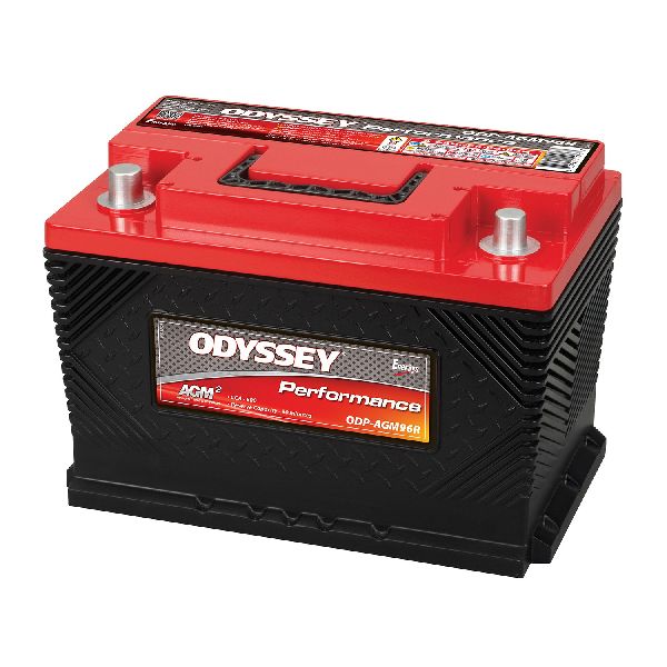
Aftermarket price range: $150-$400 for a mail-in repair service - Battery — A weak or failing battery is a very common cause of communication codes due to unstable voltage.
Trusted brands: Motorcraft, Interstate, DieHard
OEM price range: $180-$250
Aftermarket price range: $150-$220
Related Codes That Often Appear With This One
- U0101 — Lost Communication with TCM. The Transmission Control Module (TCM) is on the same network. If the entire network is down due to a gateway (IPC) or wiring fault, communication will be lost with multiple modules simultaneously.
- U0121 — Lost Communication with ABS Control Module. The ABS module is also on the high-speed CAN bus and will lose communication during a network-wide failure.
- U0140 — Lost Communication with Body Control Module. Further evidence of a network-wide communication failure rather than an isolated PCM issue.
- U0073 — Control Module Communication Bus "A" Off. This code indicates the entire network is down, which often accompanies a U0100 when the cause is a gateway module, power/ground, or bus wiring short.
Technical Service Bulletins (TSBs) & Recalls
- While no specific TSB for U0100 on this exact platform was found, TSBs for similar network issues on other Ford models (e.g., TSB 23-2123, SSM 53994 for Super Duty trucks) consistently point to power supply, ground connection, and wiring harness connector problems as the root cause, reinforcing the diagnostic priority away from module failure.
- Manufacturer records for related Ford platforms also highlight that the transmission PRNDL/S gear selector on the instrument cluster may flash when U0100 and U0101 are present (NHTSA ODI #11102327).
Platform-Specific Known Issues
- Instrument Cluster Solder Joint Failure: The most prevalent issue for U0100 on this platform. The solder joints on the main electrical connector of the instrument cluster's circuit board crack over time from thermal cycles and vibration. This creates an open circuit, severing communication on the CAN bus and causing a no-start and dead gauges. A firm tap on the dash can temporarily restore the connection, which is a definitive diagnostic clue.
Mechanic-Grade Diagnostic Values
- CAN Bus Resistance — expected: ~60 Ω. Failure: 120 Ω indicates an open circuit or one missing terminating resistor. ~0 Ω indicates a short between CAN High and CAN Low wires.
- CAN Bus Voltage (Healthy Communication) — expected: CAN High: 2.5V to 3.5V. CAN Low: 1.5V to 2.5V. The signals should be a clean mirror image of each other on an oscilloscope.. Failure: Voltages stuck high (e.g., near system voltage) or low, or a lack of signal switching indicates a bus fault.
- Battery Voltage (Key Off) — expected: 12.4V or higher. Failure: Below 12.0V suggests a discharged or weak battery that can cause module communication issues.
- Ground Circuit Resistance — expected: Less than 5 Ω (ideally < 0.2 Ω). Failure: High resistance indicates a corroded or loose ground connection, which can cause floating voltages and communication errors.
- Instrument Cluster (IPC) Power Supply — expected: Greater than 10V. Failure: Low or no voltage indicates a blown fuse (SJB Fuse 26) or an open in the power supply wire.
Scan Tool Commands That Help
- Ford IDS / FORScan: Instrument Cluster Self-Test — To quickly check the functionality of the gauges, warning lights, and LCD display without external tools. It can be initiated by holding the trip/odometer reset button while turning the ignition to the 'ON' position.
- Ford IDS / FORScan: Programmable Module Installation (PMI) — This function is required when replacing the Instrument Cluster (IPC) or Powertrain Control Module (PCM). It downloads the configuration data (As-Built data) from the old module (if possible) and uploads it to the new one, and performs security procedures.
- Ford IDS / FORScan: Parameter Reset — This is a critical step after installing a new or used IPC or PCM. It synchronizes the Passive Anti-Theft System (PATS) security information between the module and the ignition keys. The vehicle will not start until this is completed. You must have at least two working keys.
Wiring & Ground Locations

- G100 — Left front of the engine compartment, on the inner fender.. This is a primary chassis ground point for multiple components in the engine bay, including the Battery Junction Box (BJB). Corrosion here can cause widespread electrical issues.
- G101 — On the 3.0L engine, it's located near the battery. On the 2.5L, it's at the rear of the engine.. Provides a key ground path for the engine and its associated modules. A poor connection can interrupt power to the PCM.
- G104 — At the left front corner of the engine compartment, near the Battery Junction Box (BJB).. Another critical ground point for the front-end electrical system. Its proximity to the BJB makes it essential for stable module power.
- IPC Connector C220 — The main 26-pin connector on the rear of the Instrument Panel Cluster.. This connector carries all power, ground, and network signals for the IPC. Pin 5 (BK-BU wire) is a key ground. Pin 21 (YE-RD wire) is the keep-alive power. Pins 25 (GN-BU) and 26 (WH-GN) are the HS-CAN bus lines.
- Data Link Connector (DLC) — Under the driver's side dashboard.. This is the primary diagnostic port. Pin 6 (CAN High) and Pin 14 (CAN Low) are used to test the entire network's resistance and voltage. Pin 16 is battery power, and Pin 4/5 are grounds.
Real Owner Repair Stories
- YouTube video on a 2010 Ford Escape (2010 Ford Escape) — No-crank condition. The key would turn but did not feel like it was engaging the 'start' position.
❌ Tried (didn't work) The previous mechanic had already replaced the ignition switch.
✅ What actually fixed it The ignition lock housing was worn out. The internal rod that connects the key cylinder to the electrical ignition switch had excessive play and was not traveling far enough to command a start. Replacing the entire ignition lock housing assembly resolved the no-crank issue.
Documented NHTSA Reports
- An owner reported a loss of communication where the dealership found fault codes U0100 and C1963, indicating the ABS had lost communication as well (NHTSA ODI #10721046).
- In another instance, a technician found the TCM inoperative with codes U0101 and U0100, requiring a TCM replacement and clutch learning procedure (NHTSA ODI #10670375).
- NHTSA ODI #11535218 describes a situation where a code reader identified U0100 and U0151 despite the battery and starting system testing in good working order.
- A report involving a Ford engine noted U0100 appearing alongside EGR-related codes P0404 and P0405 during a diagnostic test (NHTSA ODI #10583652).
Diagnostic Flowchart

Used vs. New Parts: Buying Guide for This Vehicle
When a used part is the smart pick: For the Instrument Panel Cluster (IPC), sending the original unit for repair is often the best choice as it avoids the need for programming. If a replacement is necessary, a used cluster from a junkyard is a viable, cost-effective option, but ONLY if you have access to a Ford dealer or a well-equipped independent shop that can perform the mandatory programming (PMI and PATS Parameter Reset).
Donor-vehicle mileage cap: roughly under 150000 miles for the part to have meaningful remaining life.
What to inspect on the donor part:
- Match the part number EXACTLY from your original cluster to the donor.
- Ensure the donor vehicle has the same features (e.g., message center vs. base display).
- Inspect the clear plastic lens for deep scratches or hazing.
- Ask the seller if the donor vehicle was running when the part was pulled, which suggests the cluster was functional.
OEM-only on this vehicle (don't cheap out):
- Powertrain Control Module (PCM): While aftermarket PCMs exist, using a new or remanufactured OEM unit from Ford or a reputable rebuilder like Flagship One is highly recommended to ensure correct software and compatibility. Used PCMs can be problematic due to security lockouts and software mismatches.
Aftermarket brands forum-validated for this vehicle:
- For IPC repair: Circuit Board Medics, Automotive Circuit Solutions, XeMODeX.
- For scan tools: FORScan with a compatible OBDLink adapter is a powerful DIY option for diagnostics and some programming functions.
Brands owners have reported issues with on this vehicle:
- Generic, unbranded eBay/Amazon instrument clusters should be avoided as they often have quality issues and may not be programmable.
Real Owner Stories
Aggregated from forums and TSBs cited above. Mileages and costs reflect what owners reported in those sources.
2008-2012 Ford Escape
Symptoms: A no-start condition with no communication, accompanied by codes U0100 and U0155.
What fixed it: The faulty instrument cluster was repaired. The issue was confirmed using the 'tap test' on the dashboard.
Source hint: escape-city.com: Another no start, no communication U0100, U0155 solved
2008 Ford Escape
Symptoms: The vehicle won't start, there is no bus communication, and the gauges are dead.
What fixed it: The confirmed fix for many owners with these symptoms was addressing the instrument cluster's internal failure.
Source hint: ford-trucks.com: 2008 Escape won't start - no bus communication
Related OBD-II Codes
Frequently Asked Questions
My 2009 Escape won't start and the gauges are dead. Is it the main computer (PCM)?
I tapped the dashboard above the gauges and the car started. What does this mean?
Are there specific ground wires I should check first for a U0100 code on my Ford Escape?
How can I test the CAN bus wiring myself on my Escape?
My mechanic says the instrument cluster needs to be replaced. Is repairing it an option?
Does this U0100 instrument cluster issue also affect the Mercury Mariner or Mazda Tribute?
Helpful Videos
We Have This Part in Stock

The information in this article is provided for general reference and educational purposes only. Vehicle specifications, procedures, and part compatibility can vary by production date, trim level, and region. Always consult your vehicle's factory service manual and verify part numbers before purchasing or performing repairs. Safety-critical components such as airbags, seat belts, and braking systems should be installed by a qualified professional.
- Ford Escape:
- 🎬 Helpful Videos
- 🛍️ Shop This Part
- What's Unique About the 2008-2012 Ford Escape
- Symptoms You May Notice
- Most Likely Causes
- Rare But Worth Checking
- Diagnosis Steps
- Parts You'll Likely Need
- Related Codes That Often Appear With This One
- Technical Service Bulletins (TSBs) & Recalls
- Platform-Specific Known Issues
- Mechanic-Grade Diagnostic Values
- Scan Tool Commands That Help
- Wiring & Ground Locations
- Real Owner Repair Stories
- Documented NHTSA Reports
- Diagnostic Flowchart
- Used vs. New Parts: Buying Guide for This Vehicle
- Real Owner Stories
- 2008-2012 Ford Escape
- 2008 Ford Escape
- Related OBD-II Codes
- Frequently Asked Questions
- 🎟️ Get 5% Off