

U0073 on 2007-2014 GMC Yukon: Control Module Communication Bus 'A' Off Causes and Fixes
On a 2007-2014 GMC Yukon, code U0073 almost always points to a wiring problem on the high-speed CAN bus, not a failed module. The most common cause is corroded or damaged wires under the driver's side door sill plate or carpet due to water intrusion. This is a well-documented issue on the GMT900 platform. Fixing the wiring is a low-cost DIY, but diagnosis can be complex.
- U0073 on a 2007-2014 Yukon is a serious network communication failure.
- The most likely cause is NOT a bad computer, but corroded wiring under the driver's side carpet due to water leaks.
- Before replacing any expensive parts, perform a visual inspection of the wiring harness in the driver's footwell and check the CAN bus resistance (should be 60 ohms).
- Due to the complexity of network diagnostics, professional help is strongly recommended if the problem isn't obvious wiring damage.
What's Unique About the 2007-2014 Gmc YUKON

The GMT900 platform, which includes the 2007-2014 Yukon, Tahoe, Suburban, Silverado, and Escalade, is well-known for issues related to this code, as highlighted in GM's own technical service bulletins. The primary vulnerability is the routing of the main CAN bus wiring harness through a channel under the driver's side sill plate and carpet. This area is prone to water collection from leaking windshield seals, sunroof drains, or door seals. This design makes the twisted-pair CAN wires highly susceptible to corrosion and damage over time, which is the leading cause of U0073 on these specific trucks and SUVs.
Diagnostic Flowchart

Tap your situation to follow the diagnostic path that matches what you're seeing on this vehicle.
Symptoms You May Notice

- Multiple warning lights on the instrument panel (Check Engine, ABS, StabiliTrak)
- "Service StabiliTrak" or "Service Traction Control" messages on the DIC
- Transmission may not shift correctly, may feel stuck in gear, or go into limp mode
- Gauges on the instrument cluster fluctuating wildly or dropping to zero
- Door locks cycling intermittently and random chimes
- Engine may not start or crank, or may stall while driving
- Loss of power features like windows, radio, or HVAC controls
- Scan tool has difficulty communicating with multiple modules
- Replacing the ECM or BCM without confirming a wiring fault first. The symptoms often point to a bad module, but the root cause is far more likely to be the wiring connecting them.
- Replacing the transmission's internal TCM (TEHCM) when the fault is in the external vehicle harness leading to the transmission.
Most Likely Causes

- Corroded or Damaged CAN Bus Wiring 🔴 High Probability The main communication harness is routed in a wiring trough under the driver's side carpet and sill plate, an area known for water leaks from the windshield, sunroof, or door seals. This moisture wicks into the harness and causes the twisted-pair CAN wires (typically a Tan wire and a Tan/Black wire) to corrode and fail, creating an open in the circuit.
How to confirm: Pull up the driver's side plastic sill plate and lift the carpet to visually inspect the large wiring harness, particularly near the B-pillar and where the harness curves up towards the dash. Look for green/white corrosion, swelling, or obvious breaks. With the battery disconnected, use a multimeter to check for resistance across the two CAN wires at the OBD-II port (pins 6 and 14). A healthy network has two 120-Ohm terminating resistors in parallel, so it will read ~60 Ohms. A reading of ~120 Ohms or infinite resistance (OL) points to a break in the wiring or a faulty terminating resistor.
Typical fix: Cut out the damaged section of wire, solder in a new piece of same-gauge wire (preferably a twisted pair), and protect the repair with adhesive-lined heat-shrink tubing. Ensure the area is completely dry and address the source of the water leak to prevent recurrence.
Est. part cost: $5-$20 - Faulty Control Module 🟡 Medium Probability While less common than wiring issues, an internal failure in a major module (like the BCM, ABS, or TCM) can cause it to broadcast junk data or short out the network, pulling it down. The BCM is a frequent suspect as it acts as a gateway between different data buses.
How to confirm: This requires an advanced scan tool that can show network module status. The diagnostic process involves unplugging modules one by one from the CAN bus until communication is restored to the remaining modules. The module that, when unplugged, allows the network to function again is the faulty one.
Typical fix: Replace the failed module. Note that many modules, like the BCM or ECM, will require programming by a dealer or a qualified shop with GM-specific software (Tech2/MDI).
Est. part cost: $200-$800 - Poor Ground Connection ⚪ Low Probability Vibration and corrosion can weaken critical ground connections for the control modules over time. A poor ground can cause a module to malfunction and disrupt the network.
How to confirm: Locate the main ground points for the BCM, ECM, and instrument panel (e.g., on the A-pillar behind the driver's kick panel). Check that they are clean, tight, and free of corrosion or undercoating.
Typical fix: Remove the ground bolt/nut, clean the contact surfaces to bare metal, and re-secure the connection. Applying dielectric grease can prevent future corrosion.
Est. part cost: $0-$5 - Weak or Failing Battery ⚪ Low Probability Low system voltage during startup can prevent modules from initializing correctly, causing temporary communication faults and a flurry of 'U' codes.
How to confirm: Test the battery with a multimeter. It should read at least 12.4 volts with the engine off. Have the battery and charging system professionally load-tested, as a battery can show good voltage but fail under load.
Typical fix: Replace the weak battery.
Est. part cost: $150-$250
Rare But Worth Checking
- Pinched Wiring Harness: In some GM trucks, the dash harness can get pinched between a mounting bracket and the body, eventually causing wires to short out. This is less common but worth checking if no corrosion is found.
- Faulty Aftermarket Electronics: Improperly installed remote starters, alarms, or trailer brake controllers can interfere with the CAN bus network and trigger a U0073 code. 🎬 Watch: A helpful guide on U0073 causes and common fixes. If you have recently installed any aftermarket device, try disconnecting it to see if the problem resolves.
- Blown Mega Fuse After Jump Start: A voltage spike from an improper jump start can blow the main 175-amp mega fuse on the battery distribution block. This is a protective measure to save the modules, but it will take the network down and cause a U0073 code. The fuse must be tested for continuity and replaced if open.
Diagnosis Steps
- Scan for all DTCs in all modules. Note which modules are not communicating. A flood of 'U' codes points to a network-wide problem.
- Check for any related Technical Service Bulletins (TSBs). TSB #08-07-30-021H is directly relevant to this platform and code.
- Test the battery and charging system to rule out low voltage issues. Ensure voltage is stable above 12.4V (engine off) and 13.7V+ (engine on).
- Disconnect the battery. Access the OBD-II port and measure the resistance between Pin 6 (CAN High) and Pin 14 (CAN Low). A healthy network will read approximately 60 ohms.
- If resistance is 120 ohms, it means one of the two terminating resistors is not seen by the network, usually due to an open circuit (broken wire). If resistance is infinite (OL), there is a break in the wiring close to the port.
- If resistance is 120 ohms or OL, proceed to the most likely failure point: Remove the driver's side front door sill plate and peel back the carpet. Carefully inspect the large wiring harness in the plastic trough for signs of corrosion (green powder), swelling, or physical damage.
- If wiring appears damaged, repair the affected wires. Solder and adhesive-lined heat-shrink tubing are recommended for a durable, moisture-proof repair.
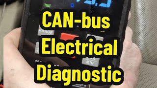
- If the wiring looks pristine and resistance was correct (~60 ohms), the issue may be an intermittent fault or a faulty module. This requires a more advanced diagnostic approach, such as using a scan tool to monitor module status while performing a wiggle test 🎬 See this walkthrough for diagnosing GM CAN-bus electrical faults. on the harness or disconnecting modules one by one.
- After any repair, perform a global reset by touching the disconnected battery cable ends together for 60 seconds to drain all module capacitors, then reconnect and clear all DTCs. Perform a test drive to ensure the issue is resolved.
Parts You'll Likely Need
- Wiring Repair Supplies — This code is most often caused by corroded or broken wires in the main harness, requiring sections to be cut out and replaced.
Aftermarket price range: $5-$20 - Body Control Module (BCM)
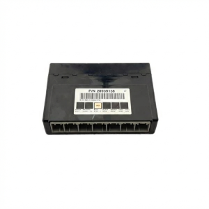
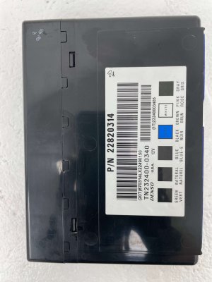
(OEM #15940214, 25896299, 22860591 (Part numbers are VIN-specific, always verify))— If a module is confirmed to be at fault, the BCM is a common culprit as it acts as a gateway for many communication networks. Requires programming upon replacement.
Trusted brands: ACDelco (Genuine GM)
OEM price range: $250-$400
Aftermarket price range: $200-$350
Related Codes That Often Appear With This One
- U0100 — Lost Communication with ECM/PCM
- U0101 — Lost Communication with TCM
- U0121 — Lost Communication with ABS Control Module
- U0140 — Lost Communication with Body Control Module
- P0700 — Transmission Control System Malfunction (often requested by the TCM when it loses communication)
Technical Service Bulletins (TSBs) & Recalls
- Bulletin #08-07-30-021H: Addresses 'Loss of High Speed GMLAN Communications' on a wide range of 2007-2014 GM trucks and SUVs. It lists symptoms like gauge fluctuation, intermittent no-crank, shifting problems, and DTCs U0073, U0100, U0101, U0121, and U0140, pointing to wiring and connection issues.
Platform-Specific Known Issues
- A known issue documented in TSB #08-07-30-021H involves water intrusion leading to corrosion in the wiring harness channel under the driver's sill plate, causing a host of communication DTCs including U0073, along with symptoms like gauge fluctuation and shifting problems.
- Owners on forums frequently report finding the green-crusted, corroded CAN bus wires (Tan and Tan/Black) in this specific location after experiencing the exact symptoms described in the TSB.
Mechanic-Grade Diagnostic Values
- CAN Bus Resistance (at OBD-II Pins 6 & 14, battery disconnected) — expected: ~60 Ohms. Failure: A reading of ~120 Ohms indicates an open circuit or one terminating resistor is offline. A reading of 0 Ohms or very low resistance indicates the CAN High and Low wires are shorted together.
- CAN High Voltage (Pin 6 to ground, key on) — expected: Toggling between 2.5V (recessive) and 3.5V (dominant). Failure: Flatline voltage, or voltage spiking to battery voltage (9V+), indicates a short or faulty module pulling the bus high.
- CAN Low Voltage (Pin 14 to ground, key on) — expected: Toggling between 2.5V (recessive) and 1.5V (dominant). Failure: Flatline voltage, or voltage dropping to 0V, indicates a short to ground or faulty module.
Scan Tool Commands That Help
- Tech2 / GDS2: Isolate Bus by Disconnecting Fuses — When resistance is correct (~60 ohms) but communication is still down, this helps find a module that is corrupting the bus. Remove the battery feed fuse for each high-speed LAN module one at a time while monitoring the scan tool to see if communication with other modules returns.
- Physical Diagnosis (no tool needed): Isolate Bus Halves via Connector C3(X3) — This is a primary professional diagnostic step to quickly determine which half of the vehicle's network contains the fault. Disconnecting the green C3(X3) connector on the back of the instrument panel junction block (fuse box) splits the bus. If communication is restored to the ECM, TCM, and BCM, the fault lies in the disconnected portion of the harness/modules.
Wiring & Ground Locations

- G300 — Under the vehicle at the driver door on a body mount.. A GM TSB specifically calls out checking this ground for being loose or having undercoating between the eyelet and the frame, causing a poor connection and intermittent network issues.
- G102 — On the left front of the engine, near the cylinder head.. This is a primary engine-related ground. A TSB for Hybrid models with U0073 specifically mentions checking G102 for a clean and tight connection.
- SP205 / SP206 — Splice packs located up under the dash, above the emergency brake pedal area.. These splice packs are junction points for the data bus wires. They are critical for advanced diagnostics, allowing a technician to isolate specific legs of the network to find a fault, but are often difficult to see or access.
- C3 (X3) Connector — A green connector on the back of the Left I/P Junction Block (the interior fuse box).. This is the most important diagnostic connector for splitting the high-speed CAN bus. Disconnecting it separates the BCM/ECM/TCM from the rest of the modules on the bus, instantly telling a technician where to focus their search.
- G201 — In the upper left corner of the instrument panel, near the A-pillar, behind the dash.. This is a key ground point for instrument panel components, which are often the first to show symptoms of a CAN bus failure.
Real Owner Repair Stories
- YouTube channel "2022 2 22" (2012 GMC Yukon Denali) — Multiple warning lights, clicking relays, CAN bus voltage spiking to 9V with key on.
❌ Tried (didn't work) Initial check showed 64 ohms, which seemed okay., Wiggle testing harnesses did not consistently replicate the fault.
✅ What actually fixed it The technician unplugged modules on the high-speed CAN bus one by one. When the ABS control module was unplugged, the clicking stopped and the CAN bus voltage waveform on the oscilloscope immediately returned to normal. Replacing the faulty ABS module resolved the issue. - Tahoe Yukon Forum user (2007-2014 generation (specific year not mentioned)) — No-start condition, scan tool communication issues.
❌ Tried (didn't work) A backup mechanic suggested replacing the ECU for $900 without proper diagnosis.
✅ What actually fixed it The owner measured the CAN bus resistance and found it was 121.6 Ohms instead of the correct ~60 Ohms. This confirmed an open circuit in the bus (a broken wire or a failed terminating resistor/module), preventing him from needlessly replacing the ECU and pointing toward a wiring repair or module isolation test. - Tahoe Yukon Forum user (2008 Yukon XL) — No start, voltmeter pegged low, even though battery voltage was 13V.
❌ Tried (didn't work) Leaving doors open for an extended period (45 mins) while cleaning triggered the fault.
✅ What actually fixed it Disconnecting the battery cable for 10 seconds and reconnecting it allowed the vehicle to start and run normally. This indicates the fault was a temporary glitch, likely a control module that failed to 'wake up' or 'go to sleep' correctly, causing a temporary bus failure.
"I Checked Everything" — The Actual Cause
- The network equivalent of a 'smoke test clean' scenario is when the CAN bus resistance measures a perfect 60 ohms with the key off, suggesting the wiring is intact, yet the code persists. In one documented case, the resistance was ~64 ohms (acceptably close to 60), but the vehicle was still dead. The actual cause was the ABS module internally shorting the bus to a higher voltage, but only when it was powered on with the key. The resistance test, performed with the power off, could not detect this type of fault. An oscilloscope was required to see the voltage corruption when the key was turned.
OEM Part Supersession History
15837419, 15948439, 20864768, and others→22860591, 25934763— Standard part evolution and consolidation for the Body Control Module (BCM).
Heads up: This part is NOT plug-and-play. It must be programmed to the vehicle's VIN using GM-specific software (Tech2/GDS2) after installation. Failure to program will result in a no-start condition or malfunctioning features. Always verify the correct part number with the vehicle's VIN before ordering.
Model Year Variations Within This Range
- 2007.5-2014: In mid-2007, GM replaced the older 'Class 2' single-wire data bus for body electronics with a 'Low-Speed GMLAN' network. The Body Control Module (BCM) acts as a gateway, translating messages between the low-speed bus and the high-speed GMLAN bus (where U0073 occurs). While the U0073 fault is on the high-speed side, a failing BCM can cause issues on both networks.
Helpful Videos

We Have This Part in Stock


The information in this article is provided for general reference and educational purposes only. Vehicle specifications, procedures, and part compatibility can vary by production date, trim level, and region. Always consult your vehicle's factory service manual and verify part numbers before purchasing or performing repairs. Safety-critical components such as airbags, seat belts, and braking systems should be installed by a qualified professional.
- Gmc YUKON:
- 🎬 Helpful Videos
- 🛍️ Shop This Part
- What's Unique About the 2007-2014 Gmc YUKON
- Diagnostic Flowchart
- Symptoms You May Notice
- Most Likely Causes
- Rare But Worth Checking
- Diagnosis Steps
- Parts You'll Likely Need
- Related Codes That Often Appear With This One
- Technical Service Bulletins (TSBs) & Recalls
- Platform-Specific Known Issues
- Mechanic-Grade Diagnostic Values
- Scan Tool Commands That Help
- Wiring & Ground Locations
- Real Owner Repair Stories
- "I Checked Everything" — The Actual Cause
- OEM Part Supersession History
- Model Year Variations Within This Range
- 🎟️ Get 5% Off