

P2797 on 2009-2013 GMC Sierra 1500 Hybrid: Auxiliary Pump Circuit Guide
On a 2009-2013 GMC Sierra 1500 Hybrid, code P2797 almost always indicates a wiring problem between the Hybrid Powertrain Control Module (HPCM) and the auxiliary transmission fluid pump, not a failed pump. A GM Technical Service Bulletin specifically advises inspecting the wiring first. A common failure point is the connector located under the battery tray, which is prone to corrosion.
- P2797 on a 2009-2013 Sierra Hybrid specifically relates to the electric auxiliary transmission pump, which is vital for the Auto-Stop function.
- Before buying any parts, follow the advice in GM TSB PIP4873A: the most likely cause is a problem with the wiring harness or its connectors.
- Common symptoms include a disabled Auto-Stop system and a harsh jerk when accelerating from a stop.
- Due to the high-voltage components of the hybrid system, this repair is best left to a professional with the correct training and equipment.
What's Unique About the 2009-2013 Gmc SIERRA 1500
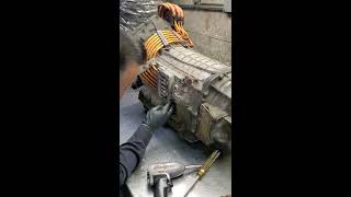
The 2009-2013 Sierra 1500 Hybrid uses a sophisticated 2-Mode (2ML70, RPO M99) hybrid transmission. 🎬 Watch: A detailed teardown of the 2ML70 hybrid transmission. This system's ability to shut the engine off at stops relies entirely on the electric auxiliary pump to keep the transmission's internal clutches engaged. Due to the known vulnerability of the pump's wiring harness and connectors, GM issued a specific Technical Service Bulletin (PIP4873A) to guide technicians. It warns them to thoroughly inspect the wiring for damage—especially at connectors, which can overheat and corrode—before considering the replacement of the more expensive pump or control module, as wiring is the most common failure point.
Diagnostic Flowchart
Tap your situation to follow the diagnostic path that matches what you're seeing on this vehicle.
Symptoms You May Notice
- Check Engine Light or Malfunction Indicator Lamp (MIL) is on
- "Service Hybrid System" message on the driver information center
- Vehicle's Auto-Stop feature is disabled or inoperative
- Harsh jerk, clunk, or surge when accelerating from a stop or during the transition from electric to gas power.
- Hesitation or delayed engagement when the gas engine restarts.
- Vehicle may lurch forward when coming to a stop.
- Vehicle may stall when coming to a stop
- Replacing the auxiliary transmission fluid pump without first performing a thorough inspection and electrical testing of its wiring harness and connectors. This is a costly mistake explicitly warned against in TSB PIP4873A.
Most Likely Causes
- Damaged or Corroded Wiring Harness 🔴 High Probability The wiring harness between the Hybrid Powertrain Control Module (HPCM) and the auxiliary pump is routed in a way that can make it susceptible to chafing, heat damage, and corrosion from road salt and moisture. The high current draw can also overheat connector pins, leading to a poor connection.
How to confirm: A thorough visual inspection of the entire harness is the first step. A key area to inspect is the connectors located directly under the 12V battery and battery tray. Unplug and check for melted plastic, green or white corrosion, or spread/pushed-out pins. Use a multimeter to perform continuity, resistance, and voltage drop tests on the pump's power, ground, and control circuits as outlined in the service manual.
Typical fix: Repair the specific damaged section of the wire or replace the corroded connector terminal. In many cases, simply unplugging, cleaning the pins with a specialized contact cleaner, and re-seating the connector firmly can restore function. If the connector is damaged, a replacement pigtail may be required.
Est. part cost: $15-$75 - Poor Connection at Pump or Control Module 🟡 Medium Probability High current draw through the connectors can lead to heat buildup, causing pins to lose tension or corrode over time, creating a poor connection. Forum users on TahoeYukonForum.com specifically mention the connectors under the battery as a frequent culprit.
How to confirm: Unplug the connectors at both the auxiliary pump and its control module (under the battery). Inspect for any signs of corrosion, melted plastic, or pins that are spread apart or pushed back into the connector.
Typical fix: Clean the connector pins with a specialized contact cleaner and apply dielectric grease before reconnecting. If pins are damaged or the connector housing is melted, the connector will need to be replaced.
Est. part cost: $20-$100
Rare But Worth Checking
- Failed Auxiliary Transmission Fluid Pump: While the code directly points to the pump, GM TSB PIP4873A explicitly warns that this is a common misdiagnosis. The pump itself is more reliable than its wiring. It should only be replaced after all wiring and connection issues have been definitively ruled out.
- Faulty Auxiliary Pump Control Module: The module that controls the pump (Part No. 24261817) can fail, but like the pump itself, this is less common than wiring faults. Diagnosis requires confirming the module has proper power and ground but is not sending the correct signal to the pump. Some TSBs have suggested replacing this module along with associated harnesses as a potential fix.
Diagnosis Steps
- Scan the vehicle's computers for all stored Diagnostic Trouble Codes (DTCs). Note if P2797 is accompanied by P0C2B or P0AC4.
- Obtain and review GM Technical Service Bulletin #PIP4873A. This document is critical for correct diagnosis and explicitly states not to replace the pump as a first step.
- DO NOT replace the auxiliary pump or control module at this stage.
- Disconnect the 12V battery. Remove the battery and the battery tray to gain access to the auxiliary transmission pump control module and its electrical connectors.
- Perform a detailed visual inspection of the wiring harness and connectors under the battery tray. Look for any signs of chafing, melting, corrosion (green/white powder), or physical damage.
- Unplug the connectors and inspect the pins for corrosion, heat damage (discoloration, melted plastic), or pins that have backed out.
- If corrosion is found, clean the pins thoroughly with an electrical contact cleaner. Let dry completely before reconnecting.
- Using a wiring diagram and a digital multimeter, test the power, ground, and control circuits for the pump. Check for proper voltage, good ground connection, and continuity on the signal wires.
- If a wiring fault is identified, repair the damaged section using approved methods (solder and heat shrink).
- If the wiring and connectors are confirmed to be good, proceed with the advanced diagnostics in the service manual, which may involve using a scan tool to command the pump on and monitor its feedback.
- Only consider replacing the auxiliary pump or its control module after all wiring and connection issues have been completely ruled out.
Parts You'll Likely Need
- Auxiliary Transmission Fluid Pump
(OEM #24253143)— This is the pump that the code monitors. It is often replaced unnecessarily but will be the required part if it has been confirmed to have failed internally after ruling out all wiring issues.
Trusted brands: ACDelco
OEM price range: $450-$600
Aftermarket price range: $350-$500 - Auxiliary Transmission Fluid Pump Control Module
(OEM #24261817)— This module powers and controls the pump. It can fail but is less likely to be the cause than wiring problems. Some bulletins suggest replacing it along with harnesses.
Trusted brands: ACDelco
OEM price range: $150-$250
Aftermarket price range: $100-$200 - Auxiliary Transmission Fluid Pump Wiring Harness
(OEM #24259588)— This harness connects the control module to the pump and is a potential point of failure. A related harness is part number 24259590.
Trusted brands: GM Genuine
OEM price range: $50-$100
Aftermarket price range: N/A
Related Codes That Often Appear With This One
- P0C2B — This code, for the 'Auxiliary Transmission Fluid Pump Control Module Feedback Signal', is often stored alongside P2797. Both codes point to a fault within the same system, and TSB PIP4873A covers diagnostics for both, treating them as a single issue.
- P0AC4 — This is a generic code meaning the 'Hybrid Powertrain Control Module has Requested MIL Illumination'. It simply indicates that the hybrid control module has detected a fault (like P2797 or P0C2B) and has asked the main engine computer to turn on the Check Engine Light.
Technical Service Bulletins (TSBs) & Recalls
- PIP4873A: Instructs technicians to diagnose DTC P0C2B with or without P2797 by first inspecting the wiring between the HPCM and the auxiliary transmission fluid pump, and specifically warns against replacing the pump as a first step.
Platform-Specific Known Issues
- A known issue on these hybrid trucks is a 'bump' or 'jerk' when transitioning between electric and gasoline engine power, which is directly linked to faults in the auxiliary pump circuit and codes like P2797.
- The primary cause identified by GM for code P2797 is not component failure, but rather issues in the wiring harness connecting the control module to the pump, as detailed in TSB PIP4873A.
- A common point of failure discussed by owners is the set of electrical connectors located under the 12V battery tray, which are prone to corrosion and overheating.
Mechanic-Grade Diagnostic Values
- Ignition Voltage at Auxiliary Transmission Fluid Pump Control Module (ATFP) — expected: 8-18 Volts. Failure: A reading outside this range indicates a foundational electrical system problem that must be fixed before diagnosing the pump circuit.
- Scan Tool: Commanded vs. Actual ATFP Speed Difference — expected: Less than 500 RPM. Failure: A difference greater than 500 RPM for more than 4 seconds will trigger DTC P2797.
- Ground Circuit Resistance — expected: 0 Ω. Failure: Any reading above 0 Ohms indicates a poor ground connection, which is a common cause of this code.
Scan Tool Commands That Help
- GDS2 (Global Diagnostic System 2): Auxiliary Transmission Pump Speed Command — This bidirectional control is used to manually command the auxiliary pump to a specific speed (e.g., 50 percent) to verify if the pump motor responds and to compare the commanded speed versus the actual speed reported back to the HPCM. This is a critical step to isolate a faulty pump from a wiring or control module issue.
- GDS2 (Global Diagnostic System 2): Data Bus Diagnostic Tool — If communication issues with the pump control module are suspected, this tool can be used to analyze the vehicle's data bus, check which modules are communicating, and help identify opens or shorts on the CAN bus network.
Wiring & Ground Locations
- G103 — On the front of the passenger side cylinder head.. This is a primary engine ground point. A poor connection here can cause a variety of electrical issues, including erratic sensor readings and module behavior that could indirectly affect the transmission control system.
- G104 — Left front corner of the engine, mounted to the left cylinder head.. Another critical engine ground. Ensuring this and G103 are clean and tight is a fundamental step in diagnosing any complex electrical fault code like P2797.
- G313 / G314 (Hybrid Specific) — G313 is on the right-hand side of the vehicle underbody, after the rear axle. G314 is mounted to the center of the rear axle.. These are grounds specific to the hybrid system (RPO HP2). A fault at these locations could directly impact the high-voltage and low-voltage control systems that manage the 2ML70 transmission and its auxiliary pump.
- Connectors under 12V Battery Tray — Under the main 12V starting battery and its plastic tray in the engine compartment.. This is the specific, well-documented failure point for the P2797 code. The connectors for the Auxiliary Transmission Fluid Pump Control Module are located here and are highly susceptible to corrosion and overheating from high current draw.
Real Owner Repair Stories
- TahoeYukonForum.com user 'lt1gmc' (2009 model year) — The classic 'bump/jerk' symptom with codes P2797/P0C2B.
❌ Tried (didn't work) Initially, just unplugging and replugging the connectors would fix the issue temporarily for a few thousand miles.
✅ What actually fixed it The final fix was to thoroughly clean the pins on the transmission pump module connectors located under the 12V battery. The user noted that high current overheats a pin, causing a bad connection, and that simply cleaning them well provided a long-term solution without replacing any parts.
OEM Part Supersession History
29543906, 29546431, 29546469, 29546636, 29547550→24261817— Standard part evolution and potential design updates.
Heads up: The replacement module (24261817) requires programming after installation.
Model Year Variations Within This Range
- 2009: GM documentation (TSB PIP4833E) notes that when replacing components on 2008-2009 models, new connectors may also be required. Specifically, if ordering the control module (24261817), you may also need connectors 24259589 and 24259590. If ordering just the pump, you may need connector 24259588. This indicates a design change in the connectors after the 2009 model year.
Helpful Videos
Used OEM Parts in Stock

New Aftermarket Parts Available




The information in this article is provided for general reference and educational purposes only. Vehicle specifications, procedures, and part compatibility can vary by production date, trim level, and region. Always consult your vehicle's factory service manual and verify part numbers before purchasing or performing repairs. Safety-critical components such as airbags, seat belts, and braking systems should be installed by a qualified professional.
- Gmc SIERRA 1500:
- 🎬 Helpful Videos
- 🛍️ Shop This Part
- What's Unique About the 2009-2013 Gmc SIERRA 1500
- Diagnostic Flowchart
- Symptoms You May Notice
- Most Likely Causes
- Rare But Worth Checking
- Diagnosis Steps
- Parts You'll Likely Need
- Related Codes That Often Appear With This One
- Technical Service Bulletins (TSBs) & Recalls
- Platform-Specific Known Issues
- Mechanic-Grade Diagnostic Values
- Scan Tool Commands That Help
- Wiring & Ground Locations
- Real Owner Repair Stories
- OEM Part Supersession History
- Model Year Variations Within This Range
- 🎟️ Get 5% Off