

P1197 on 2010-2012 Audi Q7: O2 Sensor Heater Fault Causes and Fixes
P1197 on a 2010-2012 Audi Q7 means the heater circuit for the upstream oxygen sensor on Bank 2 (driver's side) has failed. The most common fix is to replace the Bank 2, Sensor 1 O2 sensor itself. Expect to pay $70-$230 for the part and about 1-1.5 hours for labor.
- P1197 points directly to a problem with the heater in the driver's side upstream O2 sensor.
- The most likely cause is a failed O2 sensor, which is a common wear-and-tear item. The Bosch 17351 is a widely cited aftermarket replacement.
- Diagnosis is straightforward: test the resistance of the heater element in the sensor itself. A reading between 2.5-10.0 Ohms is good; an open or shorted reading confirms the sensor is bad.
- Before ordering a part, double-check that you are replacing Bank 2 (driver's side), Sensor 1 (upstream/pre-cat).
- Always check the O2 sensor heater fuse in the engine bay fuse box before replacing sensors, especially if codes for both banks appear together.
What's Unique About the 2010-2012 Audi Q7
For the first-generation Audi Q7 (and its platform mates), this fault is common enough that Audi issued a Technical Service Bulletin (TSB). The TSB #01139020337671 (also cited as 01-13-90) groups P1197 with P1196 (the equivalent fault for Bank 1), suggesting a pattern of failure for the upstream O2 sensor heaters. The TSB itself is informational, instructing technicians to contact Audi's Technical Assistance Center (TAC) before performing repairs, indicating a desire to track the failure mode. The issue is almost always a straightforward component failure rather than a complex systemic problem.
Diagnostic Flowchart
Tap your situation to follow the diagnostic path that matches what you're seeing on this vehicle.
Symptoms You May Notice
- Check Engine Light (MIL) is illuminated on the dashboard.
- Noticeably increased fuel consumption, especially on short trips.
- Failure to pass an emissions inspection.
- In some cases, a slightly rough idle or minor hesitation during the engine warm-up phase.
- Replacing the wrong oxygen sensor (e.g., the downstream Sensor 2, or the sensor on Bank 1, which is the passenger side).
- Replacing the sensor without checking the fuse first, especially if both upstream sensors fail simultaneously (P1196 and P1197).
Most Likely Causes
- Failed Oxygen Sensor (Bank 2, Sensor 1) 🔴 High Probability The internal heating element within the sensor is a common failure point due to age and repeated thermal cycles, a fact acknowledged by the manufacturer's TSB for tracking purposes. Oil or coolant leaks from above can also drip onto the sensor or its wiring, causing it to fail.
How to confirm: Disconnect the sensor and measure the resistance between the two heater circuit pins on the sensor itself. A healthy heater should have a low resistance, typically between 2.5 to 10.0 Ohms at room temperature. An infinite resistance reading (open circuit) or zero resistance (short circuit) confirms the heater has failed.
Typical fix: Replace the Bank 2, Sensor 1 oxygen sensor. An O2 sensor socket (22mm or 7/8") is required. Applying penetrating oil or gentle heat from a blowtorch may be necessary to remove the old sensor if it is seized in the exhaust manifold.
Est. part cost: $70 - $230 - Damaged Wiring or Connector 🟡 Medium Probability The wiring harness is routed near hot exhaust components and can become brittle, melted, or damaged over time. The connector, located on the firewall, can also suffer from corrosion from moisture or contamination from engine oil leaks.
How to confirm: Visually inspect the wiring harness from the sensor to the main loom for any signs of melting, chafing, or breaks. Check the electrical connector for corrosion, moisture, pushed-out pins, or oil contamination. Check for battery voltage at the appropriate pin on the vehicle-side of the harness with the key on, engine off.
Typical fix: Repair the damaged section of the wiring harness using a wiring repair kit (e.g., VAS 1978 B/C) or clean/replace the connector.
Est. part cost: $5 - $50 - Blown Fuse or Faulty Relay ⚪ Low Probability
How to confirm: Check the fuse for the oxygen sensor heaters. On the Q7, this is often located in the engine bay fuse box on the driver's side, near the firewall/windshield. For example, on some models, a 15A fuse (like SB15) protects the heater circuits. Visually inspect the fuse and check for corrosion on the contacts. If the fuse is good, a faulty relay (e.g., Engine Component Power Supply Relay J757) could be the cause.
Typical fix: Replace the blown fuse. If the fuse blows again, a short circuit exists in the wiring or the sensor itself that must be diagnosed.
Est. part cost: $1 - $20
Rare But Worth Checking
- Faulty Engine Control Module (ECM): This is very rare. The ECM's internal driver for the heater circuit can fail, sometimes due to a dead short in the external wiring or sensor. This should only be considered after all other possibilities (sensor, wiring, fuses) have been definitively ruled out by testing. 🎬 Watch: This guide shows you how to troubleshoot faulty sensors.
Diagnosis Steps
- Read the fault codes with an OBD-II scanner to confirm P1197 is the active code.
- Identify Bank 2 (driver's side in LHD vehicles) and locate Sensor 1 (the upstream sensor before the catalytic converter, visible in the exhaust manifold).
- Perform a thorough visual inspection of the sensor's wiring harness and its electrical connector on the firewall. Look for any signs of melting, corrosion, or physical damage.
- Check the O2 sensor heater fuse. Locate the fuse box in the engine compartment on the driver's side and inspect the fuse designated for the O2 sensor heaters (e.g., a 15A fuse in position SB15).
- Disconnect the oxygen sensor's electrical connector. It is typically a 6-pin black connector mounted on the firewall.
- Test the sensor's heater element: Use a multimeter set to Ohms to measure the resistance between the heater pins on the sensor side of the connector (e.g., terminals 3 and 5). A reading between 2.5 and 10.0 Ohms is good. A reading of infinite resistance (OL) or zero Ohms means the heater is burned out or shorted, and the sensor must be replaced.
- Test the vehicle-side harness: With the ignition key in the 'On' position (engine off), use a multimeter set to DC Volts to check for power (should be near battery voltage, ~12V) at the heater power pin (e.g., terminal 5) and check for a good ground at the other heater pin on the vehicle's harness connector.
- If the sensor's heater element tests bad, replace the sensor. If the harness has no power, re-check the fuse and associated relay. If the harness and sensor test good, the issue may be intermittent or, in very rare cases, the ECM itself.
Parts You'll Likely Need
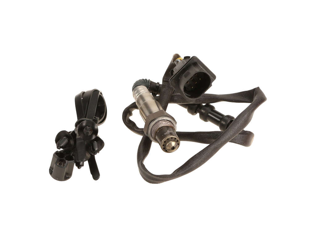
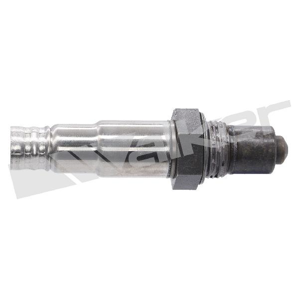
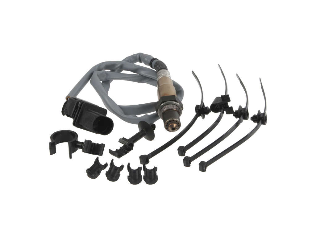
- Oxygen Sensor (Bank 2, Sensor 1)
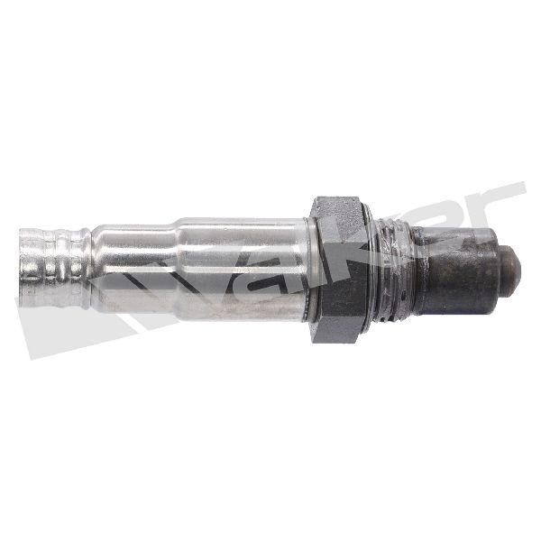
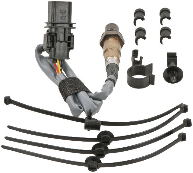
(OEM #03H906262AC)— This is the upstream (pre-catalyst) wideband sensor on the driver's side. Its internal heating element is the most common failure point for code P1197. This part number is specific to the 3.6L VR6 engine.
Trusted brands: Bosch (P/N: 17351), NGK/NTK, Denso
OEM price range: $180-$280
Aftermarket price range: $70-$230
Related Codes That Often Appear With This One
- P1196 — This is the identical heater circuit fault but for Bank 1, Sensor 1 (passenger side). It is common for both upstream sensor heaters to fail around the same time due to similar age and wear. They are grouped together in the same TSB.
Technical Service Bulletins (TSBs) & Recalls
- 01139020337671 / 01-13-90: MIL on (DTC P1196/P1197/P0135, heater circuit fault lambda sensor). This informational TSB confirms the issue across several Audi models and instructs dealers to gather data before repair, but does not provide a specific repair beyond standard diagnosis.
Platform-Specific Known Issues
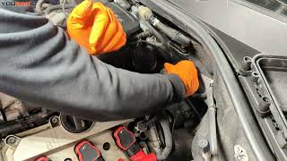
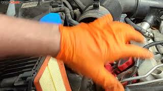
- Accessing the Bank 2 Sensor: The Bank 2 (driver's side) upstream sensor is located high on the exhaust manifold. While visible from the top of the engine bay, access can be tight. One owner reported having to cut a wrench in half to get enough leverage in the space near the firewall. Using a specialized 22mm offset or flex-head O2 sensor socket is highly recommended.
- Connector Location and Removal: The electrical connectors for the upstream O2 sensors are mounted on the firewall, behind the engine. They are often clipped into a bracket. It's necessary to un-clip the connector from the bracket before you can press the release tab to separate the two halves. 🎬 See this video to help locate your oxygen sensor connector. This prevents twisting and damaging the new sensor's wires during installation.
Mechanic-Grade Diagnostic Values
- O2 Sensor Heater Resistance — expected: 2.5 to 10.0 Ohms at ambient temperature.. Failure: Infinite resistance (OL) indicates an open circuit; near-zero Ohms indicates a short circuit.
- VCDS Live Data (Pre-Catalyst Sensor) — expected: Using graphing function, voltage should switch rapidly between rich and lean states once the engine is in closed loop.. Failure: A flat or slow-to-respond voltage reading after warm-up can indicate a poorly functioning sensor, even if the heater circuit is intact.
Scan Tool Commands That Help
- VCDS (VAG-COM): 08 - Read Measuring Value Block (MVB) — Use groups 030-036 to monitor live Lambda values and sensor readiness. This confirms if the sensor is functioning correctly after the heater has brought it to operating temperature.
- VCDS (VAG-COM): 03 - Output Diagnostic Test Mode (DTM) / Basic Settings — To actively command the O2 sensor heater circuit to turn on. This allows a technician to test the circuit's response under controlled conditions, verifying wiring and ECM control.
Wiring & Ground Locations
- O2 Sensor Connectors — Mounted on a bracket on the engine bay firewall, behind the engine.. These connectors are a common point for corrosion or damage. On some models, the Bank 2 connectors are reddish-brown, while Bank 1 connectors are black, aiding in correct identification.
- G671 — Engine compartment, on the left front long member (frame rail).. This is a primary ground connection point in the engine bay. A corroded or loose ground here can cause a variety of electrical issues, including intermittent or high-resistance faults in sensor circuits like the O2 heater.
Real Owner Repair Stories
- AudiWorld Forums user 'jcrampton' (Audi A6 (C5 platform), but with identical codes P1196 and P1197) — Check Engine Light with codes P1196, P1197, and P0134 after replacing both pre-cat O2 sensors.
❌ Tried (didn't work) Replacing both Bank 1 and Bank 2 upstream O2 sensors., Replacing the standard O2 heater fuse in the driver-side fuse panel.
✅ What actually fixed it The user found and replaced a blown maxi-fuse under the steering column, in addition to the other fuses. While the final resolution wasn't explicitly confirmed by the original poster, this discovery highlights that the power supply for the heater circuit can involve multiple fuses in different locations, which can be a point of misdiagnosis.
Model Year Variations Within This Range
- 2010: The 2010 model year was the primary year in this range for the 3.6L FSI VR6 engine in North America. The OEM part number for the Bank 2 Sensor 1 is 03H906262AC.
- 2011-2012: For these model years, the primary gasoline engine was the 3.0L TFSI supercharged V6. While code P1197 is still applicable, the oxygen sensor part number is different, and access/location may vary slightly due to the different engine architecture.
Helpful Videos
We Have This Part in Stock

The information in this article is provided for general reference and educational purposes only. Vehicle specifications, procedures, and part compatibility can vary by production date, trim level, and region. Always consult your vehicle's factory service manual and verify part numbers before purchasing or performing repairs. Safety-critical components such as airbags, seat belts, and braking systems should be installed by a qualified professional.
- Audi Q7:
- 🎬 Helpful Videos
- 🛍️ Shop This Part
- What's Unique About the 2010-2012 Audi Q7
- Diagnostic Flowchart
- Symptoms You May Notice
- Most Likely Causes
- Rare But Worth Checking
- Diagnosis Steps
- Parts You'll Likely Need
- Related Codes That Often Appear With This One
- Technical Service Bulletins (TSBs) & Recalls
- Platform-Specific Known Issues
- Mechanic-Grade Diagnostic Values
- Scan Tool Commands That Help
- Wiring & Ground Locations
- Real Owner Repair Stories
- Model Year Variations Within This Range
- 🎟️ Get 5% Off